


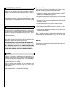
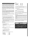
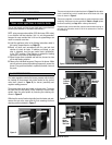
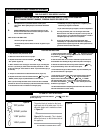
Figure 1 - Gas Supply Entry Points
10.0 PREPARING THE APPLIANCE
IMPORTANT NOTE: All gas piping must be done by a licensed plumber
or gas fitter and must conform to the requirements of the National Fuel
Gas Code NFPA 54 / ANSI Z223.1 - latest edition
Gas connection: The heater gas inlet connection is 3/8” NPT at the
regulator, located below the burner, in the center of the heater.
There are four possible entry points for the gas supply pipe-work to
enter the appliance firebox. These entry points are ‘knock out’ type holes
(shown in Figure 1).
Non-concealed gas connections may be made using the entry points
on the sides or base of the firebox. A concealed gas connection may be
made using the knock out hole in the center back of the firebox. Select
the most appropriate entry point and knock out the relevant hole.
If a concealed gas connection is to be made, the supply pipe should
always be sleeved through walls and floors using the shortest possible
route.
For concealed supply pipe routing, pipes must (where possible) be vertical
and providing there is sufficient wall thickness available, they should be
placed in pipe chases. Horizontal pipe runs should be avoided. Prior to
chasing a solid wall, an inspection should be made to note the proximity
of any cables/sockets outlets which may already be buried. Pipes must
be secured using suitable clips and protected against corrosion. Ideally
factory finished protected pipe-work and fittings should be used. Joints
should be kept to a minimum and compression fittings must not be used.
The pipe-work installation must be tested for soundness before any
protection is applied and/or the pipe-work and fittings are buried.
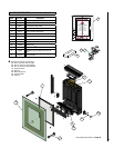
11.0 MOUNTING THE APPLIANCE
After having selected the final mounting position of the appliance, taking
into account the site requirements as specified in section 9.0 of these
instructions, the integrity of the wall, and the feasibility of the proposed
supply pipe routing, the appliance firebox may be secured to the wall.
WARNING
The wall where the appliance is to be installed must
be capable of long-term support of the total load of
the appliance. Measures should also be taken to
ensure sufficient strength to withstand the force of
earthquakes, vibration and other external forces.
To ensure customer safety, be sure to design the installation so that the
strength of both the wall and any wall fixings used are sufficient. Lennox
Hearth Products assumes no responsibility for injuries and damages that
may occur due to improper installation or handling.
The appliance should not be installed until all dry wall sanding and wall
painting has been completed.
Incorrect installation can cause the appliance to fall from the wall and
cause injury. Do not block the ventilation holes of the appliance. The
wall onto which the appliance is installed must be flat.
Install only on a vertical surface. Avoid sloped surfaces. Installation
onto anything other than a vertical wall may result in fire, damage
or injury.
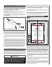
A full size fitting template is supplied to assist with wall-mounting.
Mark the positions shown as “Fixing Points” on the wall. If the appliance
is to be mounted on the inner leaf of a conventional cavity wall, or a solid
wall, drill four holes using a 5/16" masonry bit, to a depth of 1-11/16".
Insert the wall plugs provided. Note: Special "screw fixings" are not
required if installed directly into vertical studs. We recommend that
this appliance should be secured to a stud on at least one side while
the other side can be secured to the wall with the "screw fixings".
If the appliance is to be mounted on a dry lined wall or a timber framed
construction wall then special cavity screw fixings will be required which
are not supplied with this product. These should be constructed from
metal and not plastic.
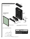
If a concealed gas connection is to be made ensure the gas supply pipe
is in it’s final position and can enter the appliance in the correct position
when the appliance is hung on the wall.
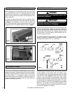
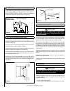
Insert the wall-mounting screws into the top wall plugs, taking care to
leave the screws protruding approximately 3/8” from the wall. Now hang
the appliance onto these screws through the two keyhole shaped holes
in the back panel of the appliance.
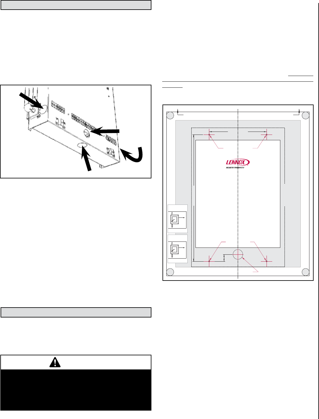
NOTE: DIAGRAMS & ILLUSTRATIONS ARE NOT TO SCALE
7
FIREBOX OUTLINE
CONTORNO DE LA CAMARA DE COMBUSTION
POSITION SPIRIT LEVEL ALONG THIS EDGE TO LEVEL TEMPLATE BEFORE MARKING OUT WALL
COLOQUE EL NIVEL SOBRE ESTE BORDE PARA NIVELAR LA PLANTILLA ANTES DE MARCAR LA PARED
PIERCE TEMPLATE TO MARK
HOLE POSITION ON WALL X 4
CENTRE LINE
CONCEALED GAS INLET
ENTRADA DE GAS OCULTA
FIXING POINTS
Elite
CVF
FIXING POINTS
PUNTOS DE SUJECION
PERFORE LA PLANTILLA PARA MARCAR
LA POSICION DE LOS 4 TALADROS EN LA PARED
PUNTOS DE SUJECION
LINEA DE
CENTRO
WALL MOUNTED VENT FREE FITTING TEMPLATE
PLANTILLA PARA LA INSTALACION DE CHIMENEAS
DE PARED SIN SALIDA DE HUMOS
IMPORTANT
THIS APPLIANCE IS TO BE WALL HUNG ONLY.
DO NOT RECESS OR INSET ANY PART OF THE APPLIANCE.
THIS TEMPLATE IS FOR THE MARKING OF FIXING POINTS ONLY.
DO NOT INSTALL THE APPLIANCE WITH THIS TEMPLATE IN PLACE.
IMPORTANTE
ESTE APARATO UNICAMENTE DEBE SER COLGADO EN UNA PARED.
NO EMPOTRE NINGUN ELEMENTO DE ESTE APARATO.
ESTA PLANTILLA SIRVE UNICAMENTE PARA MARCAR LOS PUNTOS DE FIJACION.
RETIRE LA PLANTILLA ANTES DE COLOCAR LE APARATO.
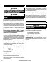
WARNING
CLEARANCES FROM COMBUSTIBLE MATERIALS
F860041/A
The following clearances must be maintained at all times.
Failure to do so may result in the risk of a fire.
For full information refer to the instruction manual
provided with the heater.
Note : Zero clearance from bottom of heater frame
required for hard combustible floors. Minimum 4”
clearance required to rugs or any fabric floor
coverings. REFER TO INSTRUCTION MANUAL
IMPORTANT : Fabrics, curtains and drapes are not
permited above the heater at any distance and within
20” of the heater sides. No combustible shelves of any
size are permitted above the heater.
Clearance to
combustible
sidewalls 4”
(both sides)
Clearance to combustible ceiling
32” measured from top of appliance
glass panel
Clearance in
front of
heater 20”
F860041/A
Deben mantenerse en todo momento los siguientes espacios
libres. El no hacerlo puede causar un riesgo de incendio.
Consulte el manual de instrucciones suministrado con este
aparato para obtener información completa.
Nota: No se requiere espacio libre desde el borde inferior del
marco del calentador en caso de pisos combustibles duros.
Se requiere un espacio mínimo de 4” entre el calentador y
cualquier alfombra, moqueta o revestimiento de suelo de
tela. CONSULTE EL MANUAL DE INSTRUCCIONES.
IMPORTANTE: No se permite la colocación de telas, cortinas y
similares por encima del calentador a cualquier distancia, ni a
una distancia de 20” de los laterales del calentador. No se
permiten estantes combustibles de cualquier tamaño por
encima del calentador.
Espacio hasta
paredeslaterales
combustibles
4” (ambos lados)
El espacio de 32” hasta un techo
combustible se mide desde el borde
superior del panel de vidrio del aparato
Espacio libre
delante del
calentador 20”
ADVERTENCIA
ESPACIO LIBRE HASTAMATERIALES COMBUSTIBLES
DO 005860/0 - ISSUE A
™
20-1/4” (515mm)
1-1/8”
(28mm)
9-3/16” (234mm)
APPLIANCE OUTLINE CONTORNO DE LA APARATO
FocalPointFires Single 24/07/08 DO 005860/0 Iss-B Lennox P23 Elite CVF fitting template
Ref. Paul West - Focal Point Fires
Artwork Size: W605 x H960
Figure 2