


NOTE: DIAGRAMS AND ILLUSTRATIONS ARE NOT TO SCALE.
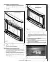
R30
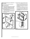
Expanded View of the Upper
Ravelle 30 Mounting Bracket
Rear View of
Backing Plate
A
Figure 2
TURN OFF THE FIREPLACE AND ALLOW IT TO COMPLETELY COOL
BEFORE PROCEEDING.
Note: Skip the steps that do not specify your model appliance.
INSTALLATION INSTRUCTIONS
Step 1. Designer™ and Revenna™ inserts - Install the Cast Surround Kit
(sold separately) per the instructions provided in the kit (see Page 1
for ordering information and Page 6 for reference information).
Step 2. Ravelle™ 30 fireplace - Pillar Face Assembly Instructions:
a) Remove the backing plate and the two upper and two lower Ravelle
30 mounting brackets from the box.
b) The two brackets with the captive screws are the upper brackets.
They are interchangeable left to right. Position the upper and lower
brackets as shown below and secure each bracket with two 5/32”
allen head screws (A in Figure 2).
c) See step 3 for instructions on mounting the backing plate to the
Ravelle 30 fireplace.
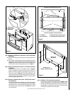
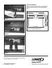
Step 3. Ravelle 30 Fireplace - Backing Plate Installation Instructions:
a) There is a 1” lip (see A in Figure 3) at the lower front of the fire-
place. The lower brackets on the backing plate have a hook (see
B in Figure 3) on their bottom edge. The face should be placed so
the hook on the lower bracket catches the 1” lip on the fireplace.
The weight of the backing plate should now be resting on the 1”
lip of the fireplace.
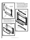
b) The upper brackets (see C in Figure 4), which were installed
on the backing plate following the instructions on the previous
page, contain a captive screw (see D in Figure 4). The captive
screws D on these brackets should be screwed into captive nuts
(see E in Figure 4) on the fireplace. A phillips head screwdriver
inserted through the large hole in the backing plate can be used
to complete this task.
AB
Figure 3
A = 1” Lip
B = Hook on Lower Brackets
2