TRIM KITS
MODEL VISTION™
INSTALLATION INSTRUCTIONS FOR INSTALLING TRIM
KITS FOR USE WITH VISION DIRECT-VENT GAS STOVES
775,290M
Rev. A, 10/2008
HEARTH PRODUCTS
KITS AND ACCESSORIES
D
R
A
F
T
1
0
/
2
7
/
2
0
0
8
KIT CONTENTS
Please ensure that all these parts are included
1 ea. Louver Assembly
2 ea. Side Window Trim
1 ea. Front Window Trim
1 ea. Ash Lip Trim
2 ea. Allen Head Screws
4 ea.
10-24 Hex Nuts
4 ea. #10 Washers
1 ea. Instruction Sheet
TOOLS NEEDED:
5/32” Allen Wrench or T-Handle Wrench
1/8” Allen Wrench or T-Handle Wrench
3/8” Open End Wrench
INSTALLATION INSTRUCTIONS
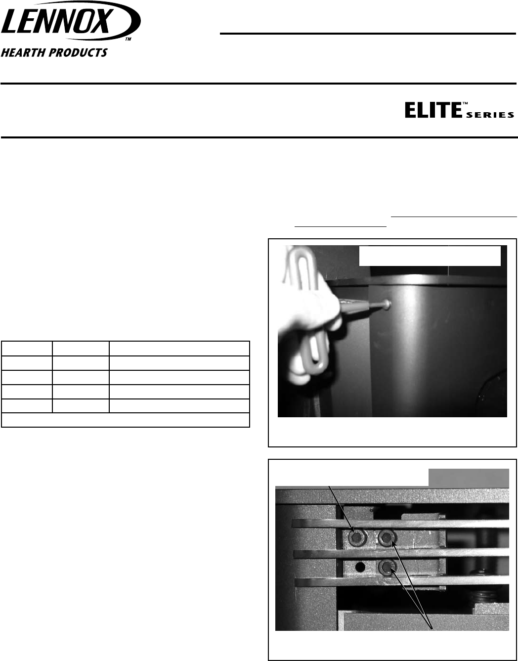
Step 1. Remove the four screws from the top of the stove - Using a 1/8”
allen wrench remove the two button head screws on the back of
the stove (see Figure 1) and using a 5/32” allen wrench remove
the two socket head screws on the front of stove (see Figure 2).
Lift off the top of the stove. Retain the screws for reinstallation
of the stove top in Step 6.
Cat. No. Model Description
75276 VISN-TRIM-B-G Black Trim Kit / Gold Handle
75277 VISN-TRIM-B-N Black Trim Kit / Nickel Handle
75274 VISN-TRIM-G-G Gold Trim Kit / Gold Handle
75275 VISN-TRIM-N-N Brushed Nickel Trim Kit / Nickel Handle
Kits Include: Matching Trim for Glass, Louvers and Ash Lip
GENERAL INFORMATION
If you encounter any problems, need clarification of these instructions
or are not qualified to properly install this kit, contact you local distribu-
tor or dealer.
Read this instruction sheet in its entirety before beginning the installa-
tion.
All of these parts may scratch and bend, great care should be used
in handling them.
ALL WARNINGS AND PRECAUTIONS IN THE INSTALLATION AND
OPERATION MANUAL PROVIDED WITH THE APPLIANCE APPLY TO
THESE INSTRUCTIONS.
TURN OFF THE STOVE AND ALLOW IT TO COMPLETELY COOL BEFORE
PROCEEDING.
CAUTION: Always ensure that plated surfaces are clean and free of
fingerprints before lighting stove. Fingerprints will leave permanent
blemishes if left on plated surface when lit. When installation is
complete, the trim should be gently cleaned with a soft cloth and
either alcohol or a household glass cleaner. Do not overtighten nuts,
overtightening can create visible dimples on the plated surface.
1
NOTE: DIAGRAMS AND ILLUSTRATIONS ARE NOT TO SCALE.
(Step 1) Using a 5/32” allen wrench, remove
the two socket head screws on the stove front.
(Step 3) Attach the louvers above the door with four supplied
screws (two on left side and two on right side of stove).
Stove Front
Stove Back
(Step 1) Using a 1/8” allen wrench remove the
two button head screws on the stove back.
Figure 1
Figure 2


