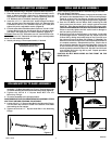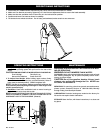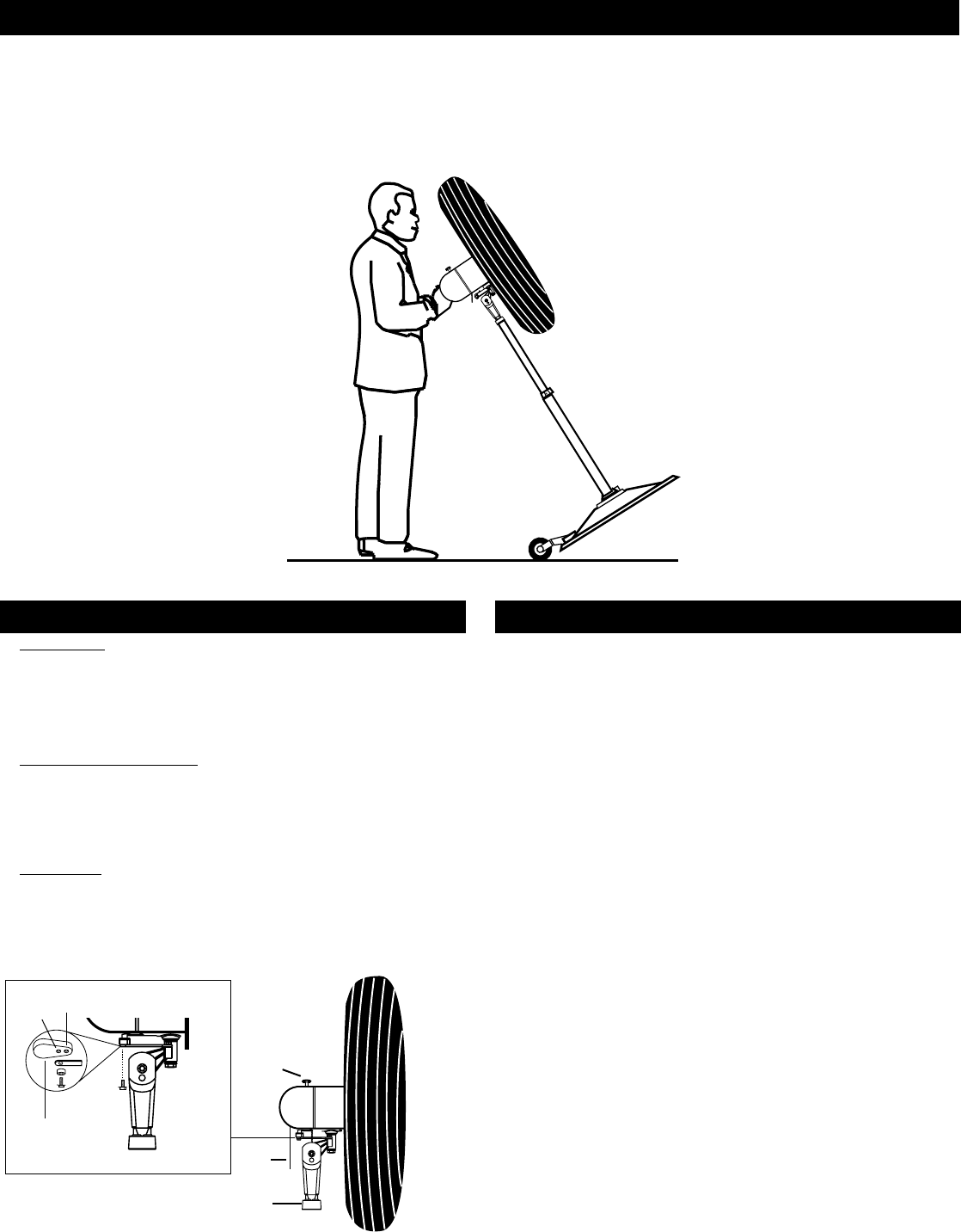
REPOSITIONING INSTRUCTIONS
Rev. A 10/11
5
5084440
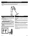
1. Disconnect ALL POWER before repositioning Fan. Never move Fan while blade is in motion.
2. Make sure Fan Head is secured by tightening 1/2” Hex Bolt and adjustment knob to secure the head assembly.
3. Make sure that the oscillation knob in the motor is in the locked down position.
4. Position and lower Fan head as shown for stability.
5. Tilt fan back onto wheels as shown. Fan is heavy and awkward; make certain to use extra care.
OPERATING INSTRUCTIONS
WARNING: ALWAYS UNPLUG THE CORD BEFORE MOV-
ING OR SERVICING.
WARNING: DO NOT IMMERSE FAN IN WATER!
CLEANING: Use a soft cloth and mild soap solution such as liquid
dish washing detergent. Dry all parts completely before recon-
necting to power supply.
CAUTION: Do not use gasoline, benzine, thinner, harsh
cleaners, etc. as they will damage the Fan. NEVER use
ALCOHOL OR SOLVENTS.
SERVICING: For servicing, other than general user maintenance,
please contact Customer Service at 800-233-0268, Monday
through Friday, from 8am-5pm Eastern.
LUBRICATION: Precision bearings are sealed at the factory for
life and do not require further lubrication.
STORAGE: Store the Fan, with these instructions, in a clean and
dry place.
MAINTENANCE
1.
2.
3.
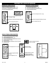
(Inset A)
Cam Gear
90˚
45˚
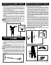
1. To Operate: Plug cord into a grounded 120V, 60 Hz outlet. Se-
lect desired operating speed with pull cord on the rear of the
motor.
CAUTION: FAN MAY START UP WHEN INITIALLY PLUGGED IN.
First Pull:High Third Pull: Low
Second Pull: Medium Fourth Pull: OFF
2. To Adjust Head Height: While holding upper column firmly,
loosen bolt on column collar (turn counterclockwise). Raise or
lower head to desired position. FIRMLY retighten bolt.
NOTE: This Fan is very heavy. Failure to securely hold onto the
head assembly while adjusting head height or head angle could
result in personal injury.
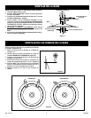
3. Oscillation: Push down oscillation knob on motor housing to
make fan head move from side to side.
NOTE: FAN IS SHIPPED WITH 90º OSCILLATION ANGLE, FOR 45º
OSCILLATION ANGLE, CONNECT THE OSCILLATION LINK TO THE
INNERMOST HOLE IN THE CAM GEAR. (Inset A)


