


+
+
Rev. A 5/05
4
5355ES
Rev. A 5/05
9
5355ES
MODEL 5355
THERMOSTAT INSTRUCTIONS
1. Pressing the ( ) or ( )
Button
will prompt the Heater into High
heat and will allow the thermostat to be set at a desired tempera-
ture. The display will shows AUTO and the word “SET”. The tem-
perature will be flashing.
2. To adjust SET temperature, press the (
) to increase the desired
temperature and the (
) to decrease the desired temperature.
3. When the air temperature reaches 3 degrees
above the SET tem-
perature, the heater will shut off.
4. When the air temperature drops 1 degree below the SET tem-
perature, the unit will come back on.
Note: It is normal for the Heater to cycle ON and OFF as it main-
tains the SET temperature.
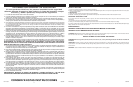
OPERATION
The Heater may be operated by the manual controls located on
the Heater (as shown in
Figure 1
) or by your remote control
(shown in
Figure 2
).
1. Place the Heater on a firm, level surface, after assembling per
this manual.
WARNING: Plastic or rubber tabs, like the feet on this unit, may
stick to furniture surfaces and/or hardwood floors. The unit may leave
a residue that could darken, stain or leave permanent blemishes on
the finish of certain furniture surfaces, including wood surfaces, and/
or hardwood floors.
2. Plug the cord set into a 120 V~ electrical outlet. Be sure plug fits
tightly in outlet.
3. When the Heater is initially plugged in, there will be a ‘beep’ and
the power light will come on indicating that there is power to the
unit. The power light will remain lit until the Heater is unplugged
from the electrical outlet.
4. Turn the Heater ON by pressing the
Power Button
( ).
5. When initially turned on, the Heater will display the current
room temperature in ° Fahrenheit. Press the (
) and
( ) but-
tons at the same time to change the display to ° Celsius. Press
the same two buttons together again to change the display
back to ° Fahrenheit.
6. The display will reflect
“Room Temp”
along with the current tem-
perature. The unit will be in the
HIGH
heat. (1500 Watts)
7. Pressing the ( )
Button
at this point will set the Heater into
LOW
heat. (900 Watts)
8. To turn the Heater OFF, press the
Power Button
( ) and unplug
the unit from the electrical outlet.
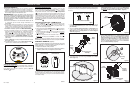
Figure 1
View of Control Panel
Oscillation Function:
The oscillation function will work in any mode. Pressing the
Oscilla-
tion Button
( ) will allow the Heater to oscillate back and forth. To
stop the oscillation, press the
Oscillation Button
( ) once more.
Timer Function:
The timer function will work in any mode. The timer function allows
you to set the length of operation from 1 hour to 8 hours. Press-
ing the
Timer Button
( ) will increase the length of operation by
1 hour each time the button is pressed. Pressing the
Timer But-
ton
( ) once more after the display reflects 8 hours will reset the
Heater to continuously running. Once the timer has been set, the
timer will count down the hours in 1 hour increments, showing on
the display the remaining operating time. The Heater will turn itself
off when the set time has lapsed. The unit can be turned back on by
pressing the
Power Button
( ).
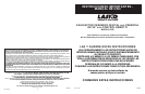
Front View of
Remote Control
Figure 2
Rear View of
Remote Control
MODELO 5355
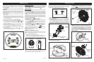
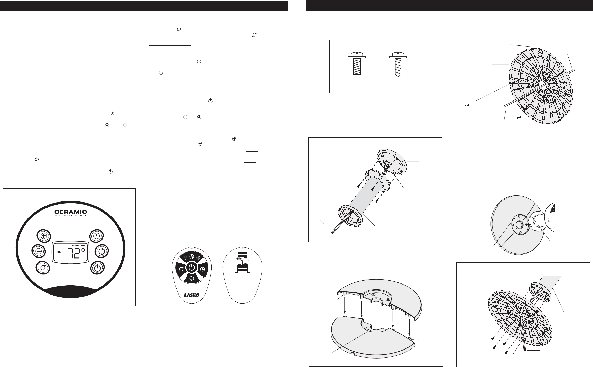
ARMADO
(Figuras 1 a 6)
Para facilitar el armado, coloque el Calefactor de manera que la
parrilla frontal y el panel de control den hacia arriba. Retire
cuidadosamente el Calefactor de su bolsa y caja.
3. Arme la base enclavando las
Protuberancias
en los
Orificios
para Protuberancias
.
(Figura 3)
5. Alinee el
Conjunto de la Base
con el
Conjunto de Soporte de
Columna
. Cerciórese de que la
Muesca de Ubicación
en el
Conjunto de Soporte de Columna
quede alineada con la
Llave
en el
Conjunto de la Base (Figura 5)
. Una el
Conjunto de la
Base
al
Conjunto de Soporte de Columna
con (4) tornillos M5
X 13 mm. Jale suavemente el
Cable Eléctrico
para que no quede
holgado, y colóquelo en el
Canal Para Cable
del
Conjunto de
la Base
.
(Figura 6)
1. Coloque el
Cable Eléctrico
en la parte inferior del Calefactor.
Pase el
Cable Eléctrico
por el centro del Conjunto de
Soporte de Columna.
2. Una el
Conjunto de Soporte de Columna
a la
Base del Motor
con (4) tornillos M5 X 13mm. Cerciórese de que la
Llave
que
está en la
Base del Motor
quede alineada con la
Muesca de
Ubicación
en el
Conjunto de Soporte de Columna
.
(Figura 2)
4. Fije las mitades de la base con (2) tornillos M4 X 13 mm. Pase el
Cable Eléctrico
por el gran orificio que se encuentra del
Conjunto
de la Base
. NOTA: El
Canal Para Cable
en la parte inferior de la
base debe estar hacia la parte posterior del Calefactor.
(Figura 4)
Tamaño Real De Tornillos
Figura 3
Protuberancias
Figura 5
Conjunto de
la Base
Conjunto de
Soporte de
Columna
Orificios
para
Protuberancias
Llave
Cable Eléctrico
Figura 1
(8) - M5 X 13mm
(2) - M4 X 13mm
Figura 2
Conjunto de Soporte
de Columna
Cable
Eléctrico
Base del
Motor
Llave
Figura 4
Cable
Eléctrico
Conjunto de
la Base
Cable
Eléctrico
Figura 6
Llave
Muesca de
Ubicación
Canal Para
Cable
Canal Para
Cable
REMOTE CONTROL
(Figure 2)
All the functions performed with the Remote Control work identi-
cally to the manual controls, except that you are unable to change
from °F to °C with the remote control.
1. Install the two “AAA” batteries supplied.
2. Do not mix old and new batteries. Do not mix alkaline, standard
(carbon-zinc) or rechargeable (nickel-cadmium) batteries.
If you lose your remote control, please call Customer Service to
order a replacement at 1-800-233-0268, Monday through Friday,
between the hours of 8:00 a.m. and 5:00 p.m. EST.