


Rev. B 11/07
4
4420ES
MODEL 4420
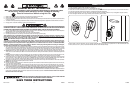
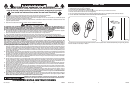
This Fan may be operated by the local controls located on
top of the unit (as shown in Figure 3) or by the Remote Control
(shown in Figure 5).
1. Carefully remove the Fan from the plastic bag and the car-
ton.
2. Place the Fan on a firm and level surface.
CAUTION: Plastic or rubber tabs, like the feet on this unit,
may stick to furniture surfaces and/or hardwood floors. The unit
may leave a residue that could darken, stain or leave permanent
blemishes on the finish of certain furniture surfaces, including wood
surfaces, and/or hardwood floors.
3. Plug the cord set into a 120 V~ outlet.
Be sure that the plug fits tightly into outlet.
When plugs fit loosely into receptacles, they may
slip partially or completely out of the receptacle
with only the slight movement of the attached cord.
Receptacles in this condition may overheat and
pose a serious fire hazard; if covered by a curtain
or drape, the fire hazard is even greater.
OPERATION (Figures 3 and 4)
4. Turn on the Fan by pressing the Power Button ( ) on the unit
or the remote control. The first time the unit is turned on, it will
be in the High speed setting.
5. SPEEDS: Adjust the speed of the Fan by pressing the Fan
Speed Button ( ), after the power is turned on. Each time the
speed button is pressed, the speed will change, from High (3),
to Medium (2), to Low (1).
6. OSCILLATION: With the Fan on, press the Oscillation Button ( ) to
start and stop the oscillation function. The oscillation function
can be used in any speed.
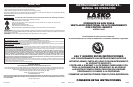
7. MULTI-DIRECTIONAL AIR VENTS: In addition to the oscillation
function, this Fan has Multi-Directional Air Vents. Adjust the Air
Vents as desired. (Figure 4)
8. NIGHTLIGHT: Press the Nightlight Button ( ) to turn on and off
the light at the base of the Fan. The nightlight function will work
when the Fan is OFF.
9. To turn the Fan OFF, press the Power Button ( ) and unplug
the unit from the electrical outlet.
Figure 3
Oscillation
Button
Power
Button
Night Light
Button
Fan Speed
Button
Figure 4
Rev. B 11/07
9
4420ES
HERRAMIENTAS NECESARIAS PARA EL
ARMADO (no incluida)
- Destornillador de Cabeza Phillips # 2
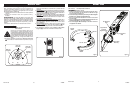
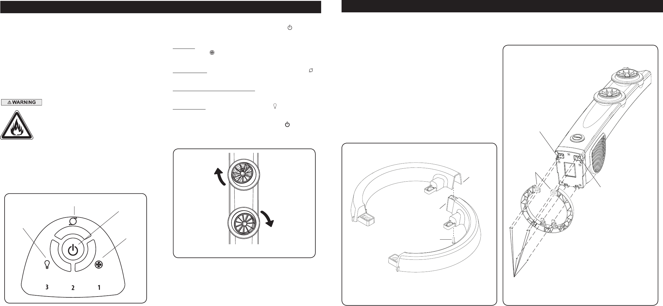
ENSAMBLADO (Figuras 1 y 2)
1. Cuidadosamente retire el Ventilador de la bolsa plástica y de
la caja. Para facilidad de ensamblado, coloque el Ventilador en
forma horizontal para que la parrilla frontal esté apuntando
hacia abajo.
2. Arme las Bases de Apoyo interconectando las Lengüetas en la
Base de Apoyo B dentro de los Lengüetas Ranuras en la Base
de Apoyo A.
3. Asegure los (1) Tornillo #8 de X 12,7 mm en los cuatro orificios
de la parte inferior de la base.
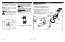
4. Alinee las Lengüetas de Alineación de la Montura de la Base
de Apoyo con las Ventilador Ranuras de Alineación en la parte
inferior del Ventilador.
5. Asegure la Montura de la Base de Apoyo a la parte inferior del
Ventilador con (6) Tornillos M5 de 12,7 mm de Largo.
Lengüetas
Lengüetas de
Alineación de la
Montura de la
Base de Apoyo
Montura de la Base
de Apoyo
Lengüetas
Ranuras
MODELO 4420
Figura 2
Ventilador
Lengüetas de
Alineación
Base de
Apoyo A
Tornillo #6 de
12,7mm
Base de
Apoyo B
Figura 1
Tornillos #6 de
12,7mm
Ventilador
Lengüetas de
Alineación