


MODELO 2648
FUNCIONAMIENTO
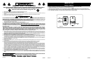
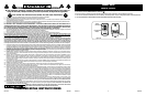
Este Ventilador puede hacerse funcionar mediante los
Controles Manuales ubicados en la parte superior de la
unidad (como se muestra en la Figura 9) o con el Control
Remoto (se muestra en la Figura 12).
1. Conecte el cable eléctrico a un tomacorriente de 120
V~.
Asegúrese que el enchufe encaje firmemente en el
tomacorriente.
Cuando los enchufes quedan flojos en los
tomacorrientes, pueden deslizarse parcial
o completamente fuera del tomacorriente
con un leve movimiento del cable adosado.
Los tomacorrientes en este estado podrían
sobrecalentarse y representar un grave
peligro de incendio; si está cubierto por una
cortina o tela, el riesgo de incendio es aún
mayor.
2. Conecte la energía eléctrica a su ventilador pulsando el
Botón Alimentación ( ).
3. VELOCIDAD DEL VENTILADOR: Ahora puede ajustar la
velocidad del ventilador al nivel deseado -baja, mediana
ó alta - pulsando el Botón Velocidad ( ).
4. OSCILACION: Empuje la perilla ubicada en la parte su-
perior de la caja del motor para hacer que la cabeza del
Ventilador se mueva de un lugar hacia otro. (Figuras 10 y 11)
5. Después de apagar el Ventilador, desconecte la unidad
del tomacorriente eléctrico.
New 9/11
10
2084237
New 9/11
3
2084237
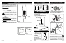
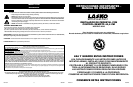
1. Take pipe assembly out of carton as shown.
(Figure 1)
2. Loosen Height Adjustment Nut turning counter clockwise. (Figure 2)
3. Raise Extension Pipe. (Figure 3)
4. Tighten Height Adjustment Nut turning clockwise. (Figure 4)
STEP 1: PIPE ASSEMBLY
STEP 2: STAND ASSEMBLY
PLACE BASE FLAT ON FLOOR
1. With a twisting motion, insert the end of the large diameter
pipe into hole in Base. (Figure 5) Turning pipe while pushing
will assure pipe is fully seated in Base.
2. For Height Adjustment:
a) Loosen Height Adjustment Nut.
b) Raise or lower Extension Pipe to desired height.
c) Tighten Height Adjustment Nut.
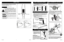
1. Place Head Assembly with
Collar onto Extension Pipe.
(Figure 6)
2. Holding Extension Pipe
firmly, twist Head Assembly
downward until seated on
Extension Pipe.
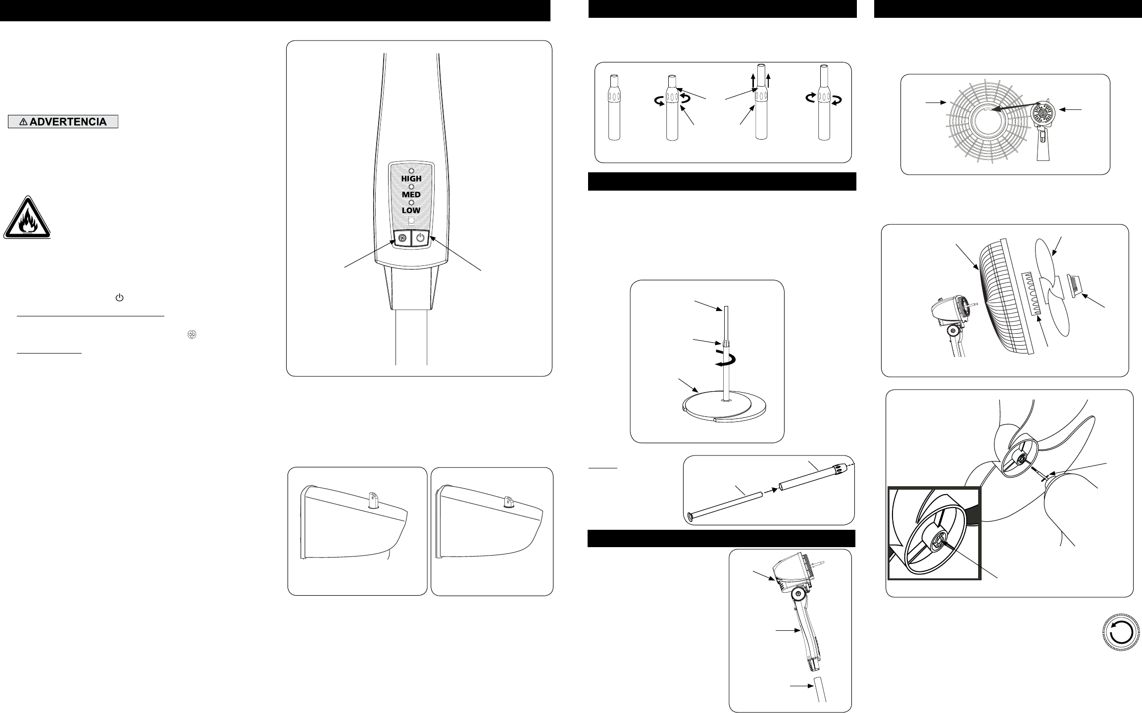
1. Tilt Head Assembly back. Put Rear Grill on Motor. (Figure 7)
2. Align tab of Plastic Rear Grill with groove on top of front
Motor cover.
STEP 4: BLADE & GRILL ASSEMBLY
3. Fully seat Rear Grill and secure with Plastic Nut turning Clock-
wise. Slide Blade onto Motor Shaft. (Figure 8) Align Groove on
blade hub with Pin on motor shaft. (Figure 8A)
4. To secure Blade, screw Spinner onto Shaft Counter
Clockwise until tight on Blade hub.
STEP 3: HEAD ASSEMBLY
Head
Assembly
Collar
Extension
Pipe
Figure 6
Botón
Alimentación
Figura 9
Figure 2 Figure 4
Figure 3
Figure 1
Height
Adjustment
Nut
Extension
Pipe
Rear
Grill
Figure 7
Motor
Rear Grill
Figure 8
Blade
Fan
Spinner
Plastic
Nut
Figure 8A
Pin
Groove
Hacia Arriba: Estacionario
Hacia Adelante: Oscilar
Figura 10
Figura 11
Botón
Velocidad del
Ventilador
5. With fan head in upright position, align Ornament of Front Grill
so it is horizontal and right side up. By starting with the top of
the grill and working down, snap Grill in place. NO GRILL CLIPS
ARE NEEDED FOR ASSEMBLY.
Extension Pipe
Height
Adjustment Nut
Base
CAUTION:
When making height adjustment after
head assembly is attached,
ALWAYS support extension pipe
with one hand, as loosening height
adjustment nut may otherwise cause
rapid fall of extension pipe and head
assembly.
Figure 5
A
B
Do Not take pipe
apart. Should pipes
become separated,
insert pipe A into
pipe B.