


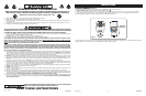

OPERATION
This Fan may be operated by the Manual Controls located on top of
the unit (as shown in Figure 5) or by the Remote Control (shown in
Figure 6).
1. Place the Fan on a rm and level surface.
CAUTION: Plastic or rubber tabs, like the feet on this unit, may
stick to furniture surfaces and/or hardwood oors. The unit may leave
a residue that could darken, stain or leave permanent blemishes on
the finish of certain furniture surfaces, including wood surfaces,
and/or hardwood oors.
2. Plug the cord set into a 120 volt outlet.
Be sure that the plug ts tightly into outlet.
When plugs t loosely into receptacles, they may slip
partially or completely out of the receptacle with only
the slight movement of the attached cord. Receptacles
in this condition may overheat and pose a serious re
hazard; if covered by a curtain or drape, the re hazard
is even greater.
3. When the Fan is plugged in, there will be a “beep” to indicate there
is power to the unit.
4. Turn the Fan ON by pressing the Power Button ( ). The Fan will
“beep” twice to indicate that the unit has been turned ON.
5. SPEEDS: Press the Fan Speed Button ( ) to desired speed
setting. Each time the Fan Speed Button is pressed, the speed
will change from Low (1), to Medium (2), to High (3). When intially
plugged in, the Fan will be in Low Speed. When the Fan is turned
OFF and ON again, the unit will resume the speed at which it was
turned OFF.
6. OSCILLATION: Press the Oscillation Button ( ) to start and
stop the oscillation function.
7. TIMER: The timer function allows the unit to be set to operate for
a length of time from 1/2 hour to 7 1/2 hours, in increments of 1/2
hour. Press the Timer Button ( ) to set the length of time desired.
Each time the timer button is pressed, the time is increased by 1/2
hour. After reaching 7 1/2 hours, pressing the timer button once
more will reset the Fan to continuous running. The lights on the
front of the unit will light up appropriately with the length of time
that the Fan is set for.
8. SLEEP: This function allows the unit to be set in Sleep Mode.
Pressing the Sleep Button ( ) once will set the unit on Low for 6
continuous hours. Pressing the Sleep Button ( ) a second time
will reset the unit to 6 continuous hours. The Oscillation Button
( ) will function when the Fan is in Sleep Mode. Pressing any
other button (Timer, Fan Speed or the Power Button) will shut off
the Sleep Mode.
9. To turn the Fan OFF, press the Power Button ( ) and unplug the
unit from the electrical outlet.
MODEL 2530
Rev. F 9/07
4
2530WGES
Rev. F 9/07
9
2530WGES
MODELO 2530
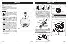
Figura 3
Conjunto de la Base de Soporte -
Vista des de Abajo
Conjunto
de la Base
de Soporte
#8 X 1/2"
Tornillos
Cable
Eléctrico
5. Fije los Tornillos (2) #8 X 1/2" en los cuatro orificios que se
encuentran en la parte inferior de la base. (Figura 3)
6. Alinee el Conjunto de la Base de Soporte con el Soporte de
Columna, cerciorándose de que el canal del cable en la parte
inferior de la base de soporte esté orientado hacia la parte posterior
del Ventilador. Ensamble el Conjunto de la Base de Soporte con
el Conjunto del Soporte de Columna utilizando los Tornillos M5
de (4) 1" de largo. Jale con cuidado toda holgura excesiva del
Cable de Electricidad e introdúzcala por el Canal Conductor de
Cable. (Figura 4)
Conjunto de Columna Para la Base
M5 X 1"
Tornillos
Conjunto De
Soportes De
Columna
Cable
Eléctrico
Canal
Conductor
de Cable
Figura 4
Conjunto
de la Base
de Soporte
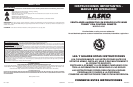
Figure 5
Remote Storage
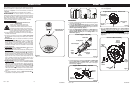
Figura 1
Cable
Eléctrico
Canales Para
Cable
Soportes De
Columna
Base Del
Motor
Muesca
Localizadora
Tornillos
M5 de 1/2"
Conjunto De Soportes De Columna
Llave
Cable
Eléctrico
Figura 2
Base de
Soporte B
Base de
Soporte A
Copas
Conjunto de la Base de Soporte -
Vista des de Arriba
Soportes De
Columna
ARMADO
1. Para facilitar el armado, recueste el Ventilador de modo que la
parrilla negra y el tablero de control den hacia arriba.
2. Localice el Cable Eléctrico en la parte inferior del Ventilador.
Coloque el Cable Eléctrico en los Canales Para Cable de los
Soportes De Columna. Encaje rmemente los Soportes De
Columna el uno con el otro de modo de formar un Conjunto De
Soportes De Columna. (Figura 1)
3. Una el Conjunto De Soportes De Columna a la Base Del Motor
con (4) Tornillos M5 de 1/2" de largo. Cerciórese de alinear la
Llave del Conjunto De Soportes De Columna con la Muesca
Localizadora de la Base Del Motor. (Figura 1)
4. Arme las Bases de Soporte, introduciendo las Copas en la Base
de Soporte A en los Oricios De Copas de la Base de Soporte
B. Pase el Cable de Electricidad por el oricio grande en el centro
del Conjunto de la Base de Soporte. (Figura 2)
4 por ventilador
4 por ventilador
2 por ventilador
Tamaño real de tornillos