


PREPARE FORSETUP
1. Begin set up near your existing network router and a
computer with high-speed Internet access.
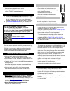
2. Unpack package contents and insert the temperature probe
into the TX60U-IT case (see diagram 1).
SETUP AND ACTIVATION
1. Locate the Activation Key Card in the package for setup
instructions and the Activation Key. A unique Activation
Key is necessary to activate your sensor and Internet
Gateway. Please keep your Activation Card for reference.
2. Visit www.lacrossealerts.com
with your Activation Key
Card to create your account and activate the product.
ACTIVATION INFORMATION:
THE INCLUDED ACTIVATION KEY is good for
1 year of ENHANCED SERVICE with early warning text
& e-mail alerts, plus 4 more years of BASIC SERVICE
for standard remote monitoring for a total of 5 years.
Lost your Activation Key Card?
Contact Customer Support:
www.lacrossetechnology.com/support/alerts
Phone: (608) 785-7920
MEASUREMENT LOG DOWNLOAD
Once the sensor is activated and building a measurement log,
you can download the data as a comma separated values
(CSV) file. You must use an application such as Microsoft
Excel® or Google Docs® that supports comma separated
values (CSV) formatted files to view the table data.
SELECT A LOCATION TO MOUNT SENSOR
• Select a location protected from water and other
precipitation. The case is water resistant, not water proof.
• Place the sensor in a dry, shaded area. Avoid locations with
direct sun, to prevent inaccurate readings.
• Fog and mist will not harm the sensor but direct precipitation
must be avoided.
• Note: Exposing the sensor case to extreme humidity may
temporarily disrupt data. The sensor case reads humidity,
but should not be submerged in water.
• Select a location within range of the Internet gateway
(see “IMPORTANT SETUP & OPERATION NOTES”).
CONFIRM CONNECTION BEFORE MOUNTING
• IMPORTANT: Before permanently mounting…Test sensor
in the desired mounting location for at least 1 hour to
confirm good reception. Confirm consistent readings on your
account at
www.lacrossealerts.com before permanently
mounting. Move the sensor closer to the Internet
Gateway if the signal is lost or not received.
• Mount the sensor after the activation process
(see “SETUP AND ACTIVATION”).
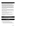
MOUNT TO WALL WITH SCREWS
1. Remove the mounting bracket
2. Place bracket over the desired location.
3. Mark mounting surface with a pencil through
the 2 holes of the bracket.
4. Screw bracket onto surface and
tighten screws to bracket.
5. Insert the sensor back into the bracket.
FREE STANDING
Attach the mounting bracket to the bottom or top of
the sensor and place it on any flat surface.
PLACEMENT OF TEMPERATURE PROBE (Optional)
• Confirm that the end of the probe cable is secured in the
socket inside the sensor (See Diagram 1).
• Insert the dry temperature probe MODEL #: D000.101.BG
on 6 Ft. cable into a refrigerator or freezer, or dry soil, etc.
for a separate reading of air or soil temperature.
• The dry temperature probe wire is not for use in water.
**An optional wet probe should be used to measure wet
environments (sold separately). Check your retailer for
availability: MODEL #: D000.102.BG or D000.103.BG
• Loosely coil and secure extra cord with a twist tie or secure
with tape (not included).
IMPORTANT SETUP & OPERATION NOTES
• The sensor has a wireless range of 200 feet (60.96 m). The
200 ft. range equates to open air with no obstructions, and
that radio waves DO NOT curve around objects. Actual
transmission range will vary depending on what is in the path
of the signal. Each obstruction (roof, walls, floors, ceilings,
etc.) will effectively cut signal range in half.
• Metal, stucco, and some types of glass can reduce signal
range by as much as ¾ or more, compared to the ½
reduction typical of most obstructions. It is possible to
receive a signal through these materials, however maximum
range will be reduced due to their tendency to absorb or
reflect a much larger portion of the sensor’s signal.
• The sensor measures and updates the temperature and
humidity on the LCD every 6 seconds.
Note: The new measurement is reported to your account at
intervals that you select using your online account.
BATTERY REPLACEMENT
1. Remove the battery cover by sliding the cover down.
2. Observing the correct polarity install 2-AAA batteries. The
batteries will fit tightly (to avoid start-up problems make sure
they do not spring free).
3. Do not mix old and new batteries.
4. Do not mix alkaline, lithium, standard or rechargeable
batteries.
5. Replace the battery cover by sliding upwards and check that
it is securely fitted.