CONTENTS
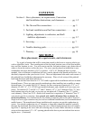
Section 1– Stove placement, air requirements, Convection
shell installation Instructions, and clearances……….. pg. 1-2
2– The flue and flue connections………………………… pg. 3
3– Fuel tank installation and fuel line connections………. pg. 4
4– Lighting, adjustments to carburetor, and draft
stabilizer adjustments………………………………. pg. 5-7
5– Servicing…………………………………………….. pg. 7
6– Trouble-shooting guide……………………………..... pg. 8-9
7– Warranty……………………………………………… pg. 10
SECTION 1
Stove placement, air requirements, and clearances
Try to pick a location that will be somewhat central in the house or room in which you
wish to install the Arctic. Due consideration of the fuel tank location, ease of fuel line installa-
tion, and flue location is wise. You will want to read the fuel tank section to get a better idea of
where to locate the tank as well as the stove. The stove must be placed on hearth that is non-
combustible, having a thickness of 3/8” or greater. A 36”x 36” hearth pad area is recom-
mended. Once a location is established, the stove can be placed on the hearth and leveled. It is
absolutely imperative that your Arctic is level. There are adjustment bolts under each corner of
the pedestal base should these adjustments be necessary. Place a level on top of the pedestal
base both directions and adjust until level.
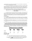
This unit has been tested to U.L. 307A and is approved for installation and use in manu-
factured homes. There are some special considerations when installing into a mobile or manu-
factured home. For model AR-10 (10” burner), the flue system must consist of a 4”,5” or 6”
diameter CLASS “A”, U.L. HT103 type insulated chimney, and a double-wall stove pipe con-
nector. For models OC-7 and OC-8 (7” and 8” burner), a 4”,5” or 6” diameter Class “A” insu-
lated chimney may also be used, or you may use an approved 4” diameter Class “L” (pellet
vent) chimney. Dura-Vent D.V.L. double-wall connector is required or 4” diameter Class “L”
vent may be used as a connector. As a general rule, smaller diameter flues are better for
draft and efficiency. For clarification see the chimney/connector table at the end of Section 2.
Single wall stove pipe connector may be used on residential installations (not for manufactured/
mobile homes). The manufactured home installation also requires an outside combustion air
source. For outside combustion air a 4” diameter or larger duct should be installed vertically
through the hearth and floor directly below the stove or horizontally through the wall connect-
ing to the 4” opening at the stove back (flex ducting may be used). Make sure there is a rodent
screen with a maximum 1/4” x 1/4” opening placed in the duct to prevent rodents from access-
ing the stove. (Continued)
1


