


Installation Manual
Installation
IMPORTANT
a. The unit should be fitted with a fused spur incorporating an all pole
disconnection device providing 3mm contact separation in all poles.
Ensure fuse, cable size and gland type are rated sufficiently for the
total load on the sounder circuit.
b. Isolate the unit from the electricity supply before removing the cover.
Only suitably qualified personnel should gain access to the unit to
perform adjustments to the tone or volume. WARNING: no user
serviceable parts contained within the unit.
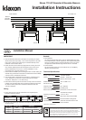
c. The sounder is installed by first mounting the base unit and making the
external wring connections to the base. The head unit then automatically
connects when it is attached to the base.
d. The sounder head is separated from the base by unlocking the four
¼-turn fasteners in the corners of the sounder. (Recommended
screwdriver: Philips No. 2, min 100mm long).
e. Note that the head only fits onto the base one way around. If a beacon
is fitted, care should be taken when mounting the base to ensure that
the beacon will be positioned in the desired orientation after the
sounder is attached.
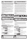
Wiring
a. Power: Note that the sounder and beacon have separate power
terminals, marked as follows:
b. Remote Tone Switching (If required): Externally link control terminals
as shown below.
EN
Sounder
Beacon (Where fitted)
Device Common (Neutral) 110V 230V
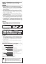
Alarm Stage Example Signal Activation
Technical Specification:
Supply Voltage Range 110/230V 50/60Hz
Current Sounder - 40mA max.
Beacon (where fitted) - 70mA
Peak Sound Level 103-115 dBA at 1m*
Number of Tones 64
Frequency Range 340 - 2900 Hz*
Volume Control 20 dBA typical
Remote Tone Switching Provision for 3 volt-free contact
activated alarm stages
Operating Temperature - 25°C to +55°C
Casing High Impact Polycarbonate/ABS
IP Rating IP66 with suitable cable glands
Synchronisation Automatic with Klaxon Nexus and
Sonos Sounders
*depends on selected tone.
TheEuropean directive “Waste Electricaland Electronic Equipment”(WEEE)
aimsto minimisethe impactof electricaland electronicequipment wasteon
theenvironment andhuman health. To conformwiththis directive,electrical
equipmentmarked withthis symbolmust notbedisposed ofin Europeanpublic
disposalsystems. Europeanusers of electricalequipment mustnow return
end-of-lifeequipment fordisposal. Furtherinformation canbe foundon the
followingwebsite: http://www.recyclethis.info/.
S2
+
-
S1
230V
~
110V
~
N
230V
~
110V
~
S
3
S2
0
S2
+
-
S1
230V
~
110V
~
N
230V
~
110V
~
S
3
S2
0
2nd Stage
3rd Stage
Beacon L
Sounder L
Common N
1st Unit
2
nd Unit
F
rom controller
To the next unit
Nexus 110 AC Sounder & Sounder-Beacon
Installation Instructions
N
N
110V
~
110V
~
230V
~
230V
~
S2
S3
Stage 1 ‘Alert’ No Connection (Default)
Stage 2 ‘Evacuate’ Link Terminal to terminal
Stage 3 ‘All Clear’ Link Terminal to terminal
Controls
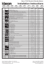
a. Tone Selection
The first and second stage alarm tones are independently set using
6-way dipswitches S1 and S2 respectively. The required settings are
shown in the table overleaf. The third stage alarm tone is pre-set to
complement the selected first stage tone as shown in the table.
b. Volume Control
The sound output of the unit can be reduced by up to 20dBA by
adjusting the potentiometer.