11
KMACS 5 MANUAL
© 2003 KMDSI Document # 041112001
2.5.2 TESTING COMMUNICATIONS
Test the communications between the diver and the
KMACS 5. With the communicator (R) switched
on, turn the speaker switch to “on” and adjust the
volume to a comfortable level for both the diver
and the KMACS 5 operator. In the 2 wire mode,
the communicator functions similarly to a citizens
band radio; i.e., the KMACS 5 operator must de-
press the push to talk switch to speak to the diver.
In the 4 wire mode, the communicator functions
like a telephone conference call; i.e., everyone on
the line can hear and speak to everyone else. In
either mode, for the diver to talk top side, it is only
necessary for him to speak into the oral/nasal mi-
crophone in his mask or helmet. If two divers will
be working together, test the cross-talk functions
at this time as well.
To extend the life of the battery, it is recommended
that the communications be used in the 4 wire mode.
Operation as a 2 wire system uses relays inside the
unit which will cause a higher battery drain.
CAUTION: In the 2 wire mode, when the
push-to-talk switch is depressed, the
KMACS 5 operator should keep all of his
communications short (10-15 seconds) at
any one time. This allows the diver to call
for assistance if necessary.
Plug the earphone connectors on the diver’s umbili-
cal into the earphone jacks on the communicator.
Plug the microphone connectors on the umbilical
into the microphone jacks on the communicator.
This will create a 4 wire system/round robin system.
Test the system and adjust all volume controls.
Unplug the earphone connectors on the diver’s um-
bilical from the communicator and reinstall them in
the connectors attached to the plugs for the micro-
phone. This will change the communicator to a 2
wire system. Test this system and adjust volumes.
If there are no communications, recheck all of the
connections to ensure they are tight at each junction.
If the KMACS 5 has been operating in a coastal en-
vironment, look for corrosion on the top side connec-
tors which may interfere with the communications.
If corrosion is evident, disassemble the connectors,
clean, and retest. If corrosion is heavy, replace the
top side connectors.
Substitute other masks or umbilicals to test for
failures in the microphones or umbilical. Substitute
one piece of new gear at a time to track the fault
down. If the fault is in the mask or helmet, replace
the earphones or microphones as needed.
If the fault is in the umbilical, disconnect the umbili-
cal and carefully inspect its length for damage. Look
for obvious nicks or cuts.
If there is physical damage to the outside of the
communications wire there probably is a break on
the inside, too. Test the continuity of the wire end-to
end with a volt-ohmmeter.
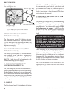
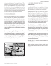
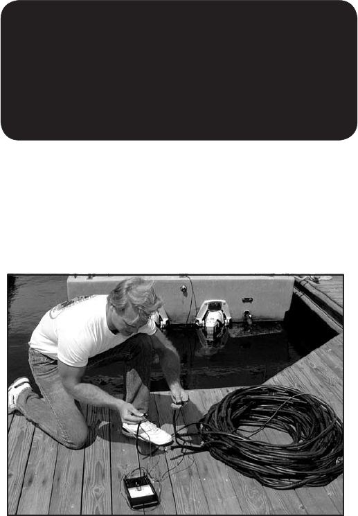
Uncoil the umbilical and lay it out flat with the two
ends close to each other. Set the volt-ohmmeter to
resistance (ohms) and hold one probe to one prong
on an umbilical connector plug and touch the other
probe from the meter to the wires (or connector) at
the opposite end of the diver’s umbilical. Upon locat-
ing the other end of the same wire, the meter should
indicate zero resistance, i.e., there is a complete,
uninterrupted circuit. If touching none of the wires
at the other end of the umbilical produces a zero
reading and all readings are infinity (∼), this indicates
a complete break in the wire. If the reading is some-
where between zero and infinity, and changes as the
umbilical is moved, this indicates a partial break, and
communications will be intermittent. In either case,
a waterproof splice must be made in the wire.
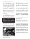
Fig. 8 Preliminary testing of the umbilical with a volt-ohm
meter to check for continuity.


