


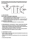
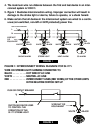
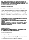
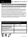

FIGURE 2: MODEL SL177 WIRING INSTRUCTIONS FOR AC QUICK
CONNECT 2-WIRE HARNESS.
Figure 2 illustrates the proper SL177 wiring. Improper connection will result in
damage to the strobe light or alarms, failure to operate, or a shock hazard.
WIRE ON STROBE LIGHT HARNESS CONNECTED TO:
BLACK . . . . . . . . . .HOT SIDE OF AC LINE
WHITE . . . . . . . . . .NEUTRAL AC LINE
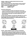
MOUNTING INSTRUCTIONS:
• A trim ring is provided on the back of the strobe light. This trim ring is
installed on the electrical box between the electrical box and the strobe light.
• Remove the trim ring from the back of the strobe light by holding the trim
ring and twisting the strobe light in the direction indicated by the "OFF"
arrow on the cover.
CAUTION THIS UNIT IS SEALED. THE COVER IS NOT REMOVABLE! After selecting
the proper strobe light location as described in section 3, and wiring the AC
QUICK CONNECT harness as described in the WIRING INSTRUCTIONS, attach the
trim ring to the electrical box (see fig. 3).
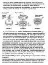
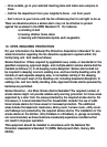
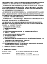
FIGURE 3: SELECT PROPER MOUNTING HOLES ON THE TRIM RING
• Use a screwdriver to punch out only the pair of holes in the trim ring that
match your type of electrical box or plaster ring. Mount the trim ring to the
electrical box using the appropriate holes. NOTE: Use the circle, square, and
octagon markings near each mounting hole in the trim ring to help you select
the correct mounting holes (see fig. 3).
Rectangular
Plaster Ring
Circular
Plaster Ring
Octagonal
Electrical Box
FIGURE 3