


9
13 14121110
Carbon Monoxide (CO) Alarm Indicator
When the CO alarm senses a dangerous level of CO, the
unit will emit a loud alarm beeping pattern. The alarm
pattern is 4 short beeps followed by 5 seconds of silence.
This cycle repeats as long as a dangerous CO conditions
exist. The red LED (Alarm) will flash the same pattern.
WARNING: For alarms equipped with 9V battery backup,
when powered by battery backup only; after four minutes,
the alarm will sound and flash only once every minute, to
conserve battery life.
If this unit is interconnected with other Kidde CO alarms,
the amber LED (Initiating Alarm) of the unit which first
detected the CO, will light and remain on until reset. The
other interconnected CO alarms will also alarm to warn
you that CO was detected.
Fire Alarm Indicator
When an interconnected Kidde smoke alarm detects
smoke, this unit will sound a smoke/fire alarm pattern of
3 long beeps, followed by 1 second of silence. This cycle
repeats as long as smoke signal persists to alert you of the
condition. If this happens, leave the premises immediately
by your escape plan and call your local fire department.
WARNING: This unit is not a smoke alarm and will not
detect smoke or fire. It will only alarm for smoke/fire if it
receives a signal from an interconnected Kidde smoke
alarm.
Note: A smoke/fire alarm will override a CO alarm
condition.
Two labels have been provided that have important
information on what to do in case of an alarm. Add the
phone number of your emergency service provider in the
space provided. Place one label next to the alarm after it
is mounted, and one label near a fresh air source such as
a door or window.
Your new Kidde carbon monoxide alarm is a sophisticated
electronic device – yet very simple to understand. The
green “Power” LED will illuminate to identify the unit is
monitoring for carbon monoxide. If it senses dangerous
levels of carbon monoxide, the red “Alarm” LED will flash
accompanied with an audible alarm pattern. (See page 13
for description of alarm patterns).
However, if interconnected to other Kidde alarms, or (If
equipped) the backup battery is low or missing, or if the
unit malfunctions, it will display other readings (and alarm
differently) to alert you of specific conditions. Please
familiarize yourself, and other family members, to the
difference between a CO alarm and an alarm signifying a
problem with the unit itself.
The table on Page 13 illustrates what the audible alarm
patterns are, and what the recommended actions are.
• Turn on the A.C. power. The green A.C. Power On Indicator
should be lit when the alarm is operating from A.C. power.
•
For alarms equipped with 9V battery backup:
Pull the
Battery Pull Tab (yellow tab protruding from unit) com-
pletely out of unit. This will automatically connect the
battery.
Tamper Resist Feature
To make this CO alarm somewhat tamper resistant, a tamper
resist feature has been provided. Activate the feature by
breaking off the four posts in the square holes in the mount-
ing plate (see Figure 3A). When the posts are broken off, the
tamper resist tab on the base is allowed to engage the mount-
ing plate. Rotate the alarm onto the mounting plate until you
hear the tamper resist tab snap into place, locking the alarm.
Using the tamper resist feature will deter children and others
from removing the alarm. To remove the alarm, press on the
tamper resist tab, and rotate the alarm off of the mounting
plate (see Figure 3B).
Mounting
• Remove the mounting plate from the back of the alarm
by holding the mounting plate and twisting the alarm in
the direction indicated by the “OFF” arrow on the alarm
cover.
• After selecting the proper location for your CO Alarm, as
described on page 5 and wiring the A.C. Quick-
Connector harness as described in Wiring, attach the
mounting plate to the electrical box. To ensure aesthetic
alignment of the alarm with the hallway, or wall, the “A”
line on the mounting plate must be parallel with the
hallway when ceiling mounted or horizontal when wall
mounted.
• Pull the A.C. Quick-Connector through the center hole
in the mounting plate and secure the bracket, making
sure that the mounting screws are positioned in the
small ends of the keyholes before tightening.
• Plug the A.C. Quick-Connector into the back of the
alarm (see Figure 2), making sure that the locks on the
connector snap into the unit. Push the excess wire
back into the electrical box through the hole in the
center of the mounting plate.
• Install the alarm on the mounting plate and twist the
alarm in the direction of the “ON” arrow on the cover
until the alarm ratchets into place (this ratcheting function
allows for aesthetic alignment). Note: The alarm will
mount to the bracket in 4 positions (every 90 degrees).
Installation
FIGURE 2
ATTACHING THE A.C. QUICK-CONNECTOR
Installation
FIGURE 3A
FIGURE 3B
A
Location
of Posts
A
TAMPER RESIST FEATURE
Operation Operation
Function LED Display Alarm Sound Unit Status Recommendation
Operation
Normal
operation
Green LED constantly on None Normal AC operation
(sensing no CO) and
with a good battery
None
Normal
operation
Green LED flashes every
7 seconds
None Normal DC operation
on 9V battery backup
Verify AC power is
restored as soon as
possible to conserve
battery. Replace battery
Carbon
monoxide
alarm
Red LED flashes with
beeps. Amber LED shows
initiating alarm
4 quick beeps,
5 seconds silence,
repeating
Alarm condition.
Dangerous
concentrations of CO
detected
Refer to alarm
procedure on
Page 17
Smoke / fire
alarm
Red LED flashes with
beeps.
3 long beeps,
1 second silence,
repeating
Receiving signal from
an interconnected
smoke alarm detecting
smoke
Evacuate by your
escape plan
Red LED flashes every
15 seconds
One short “chirp”
every 15 seconds
AC powered and low or
missing battery
Install or replace 9V
battery. Refer to
Page 14
Red LED flashes every
30 seconds
One short “chirp”
every 30 seconds
Unit malfunction Call Kidde
Customer Service
Low battery
Error / service
alarm
To test the alarm, press the Test/Reset button. If the unit is
operating properly, you should hear 4 quick beeps – followed
by 5 seconds of silence – followed by 4 quick beeps. The red
LED will flash along with the beeps and the amber LED will
illuminate. Within several seconds the unit will return to
monitor for carbon monoxide.
If interconnected to Kidde smoke alarms, pressing the
Test/Reset button on the CO alarm will have no effect on
the smoke alarms. The smoke alarms will not be tested
and will not alarm. However, when pressing the Test
button on an interconnected smoke alarm, the CO alarm
will emit a Smoke/Fire audible and visual alarm pattern of
3 long beeps, 1 second of silence, repeated. Note: You
do not need to press the Test button to take a CO reading.
Testing
WARNING: IF AT ANY TIME YOU TEST THE ALARM AND IT DOES NOT PERFORM AS DISCRIBED,
HAVE IT REPLACED IMMEDIATELY.
NOTE: REFERENCE TO BATTERY BACKUP OPERATION IS ONLY APPLICABLE TO UNITS THAT
ARE EQUIPPED WITH BATTERY BACKUP OPTION.
Red LED constantly on Constant alarm Very low battery or unit
malfunction. Unit will
not respond to CO
Replace 9V battery. If
condition continues,
call Kidde Customer
Service
Red LED flashes with
beeps. Green and amber
LED’s on
4 quick beeps,
5 seconds silence,
repeated once
Normal operation
when Test/Reset button
is pressed
CO not detected.
Alarm for test
purposes only
Error
Normal
Test/Reset
function
8
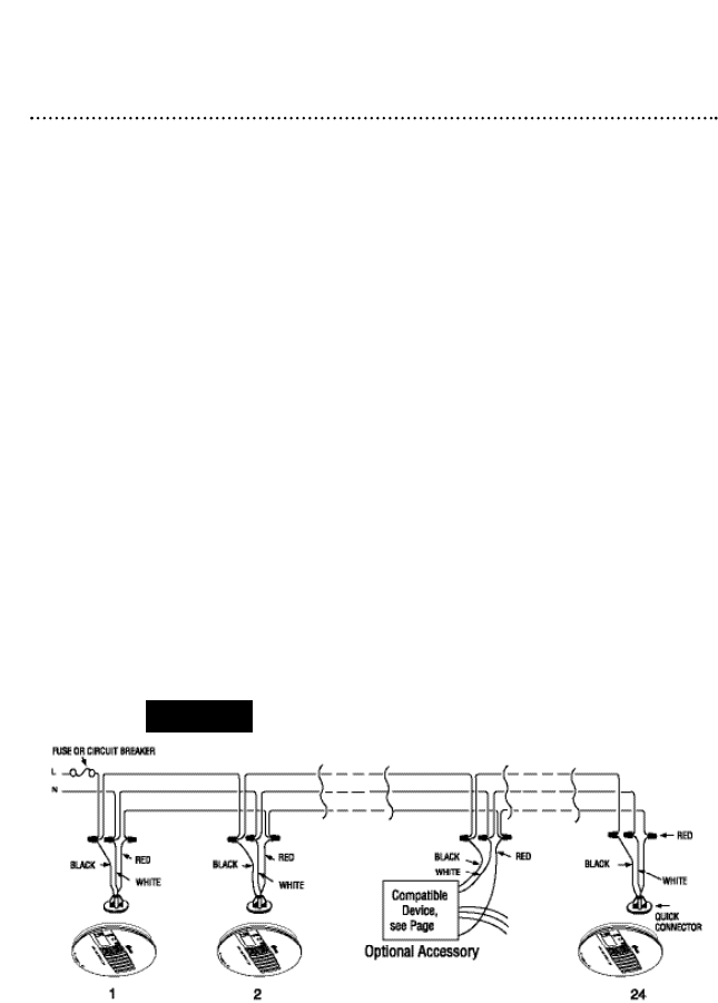
Wires on the A.C. Quick-Connector Alarm Harness:
Black Connected to hot side of A.C. line.
White Connected to neutral side of A.C. line.
Red Connected to interconnect lines (red wires)
of other units in a multiple-station set-up.
With 18 alarms interconnected, it is still possible to
interconnect up to a total of 6 remote signaling devices
and/or relay modules.
• The maximum wire run distance between the first and
last unit in an interconnected system is 1000’ (305 m).
• Make certain alarms are wired to a continuous, (non-
switched) power line. NOTE: Use standard UL Listed
household wire (18 gauge or larger as required by local
codes) available at all electrical supply stores and most
hardware stores.
Wiring
Figure 1 illustrates interconnection wiring. Improper
connection will result in damage to the alarm, failure to
operate, or a shock hazard.
CAUTION! Turn off the main power to the circuit before
wiring the alarm.
Installation
INTERCONNECT WIRING
FIGURE 1
4