


and arrow are facing up. Use the screws and anchors provided to secure the
mounting plate (use 3/16” drill bit for anchors).
4. Battery installation instructions are provided on the inside of the battery door for
Safety Light and Smoke Alarm use. To ensure proper installation of the Safety
Light and Smoke Alarm battery follow the instructions.
CAUTION! MAKE SURE TO INSTALL THE PROPER LONG LIFE BATTERY (SEE
SECTION 6) IN THE COMPARTMENT THAT POWERS THE SMOKE ALARM
AND THE ALKALINE BATTERY IN THE COMPARTMENT THAT POWERS THE
SAFETY LIGHT. REVERSING THESE WILL ELIMINATE THIS SMOKE ALARM’S
LONGLIFE BATTERY CAPABILITY AND MAY DAMAGE THE SAFETY LIGHT.
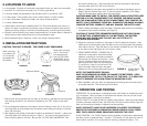
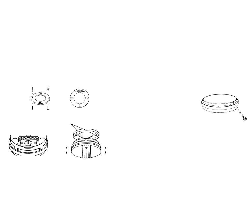
5. When installing the battery, press the battery reminder finger down into the battery
compartment and install the battery (see Figure 3).
CAUTION! IF THE BATTERY REMINDER FINGERS ARE NOT HELD DOWN
IN THE BATTERY COMPARTMENT BY THE BATTERIES, THE BATTERY
DOOR WILL NOT CLOSE, AND THE UNIT WILL NOT ATTACH TO
THE MOUNTING BRACKET.
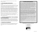
6. Alignment marks are provided on the edge of the trim plate and the alarm. After
installing the mounting plate, place the alarm on the mounting plate with the align-
ment marks lined up. Twist the alarm in the direction indicated by the “ON” arrow
on the alarm cover (see Figure 4) until it locks in place.
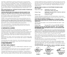
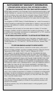
7. USING TAMPER RESIST LOCKING PIN: To
make your smoke alarm somewhat tamper
resistant, a locking pin has been provided in
the bag with the screws and anchors. Using
this pin will deter children and others from
removing the alarm from the mounting plate.
To use the pin, insert it into the hole in the
side of the alarm after the alarm has been
installed on the mounting plate (see Figure 5).
NOTE: THE TAMPER RESIST PIN WILL
HAVE TO BE REMOVED IN ORDER TO CHANGE THE BATTERIES. USE A
LONG NOSE PLIERS TO PULL THE PIN OUT OF THE HOLE. IT IS NOW POS-
SIBLE TO REMOVE THE ALARM FROM THE MOUNTING PLATE.
8. After installation, test your alarm by depressing and holding down the test button
for several seconds. This should sound the alarm.
4. OPERATION AND TESTING
OPERATION: The smoke alarm is operating once a fresh battery is installed and test-
ing is complete. When products of combustion are sensed, the unit sounds a loud
85db pulsating alarm until the air is cleared.
SAFETY LIGHT: The model 0918K has a Safety Light feature. When the smoke alarm
ionization chamber senses smoke, the 85db horn will sound and the Safety Light will
flash until the sensing chamber is cleared of smoke particles.
NOTE: THE SAFETY LIGHT IS NOT INTENDED TO SATISFY THE REQUIRE-
MENTS FOR APPROVED ILLUMINATION UNDER VARIOUS LOCAL CODES.
VERY THICK AND/OR DENSE SMOKE MAY OBSCURE THE LIGHT.
HUSH CONTROL: The “HUSH” feature has the capability of temporarily desensitizing
the alarm circuit for approximately 7 minutes. This feature is to be used only when a
known alarm condition, such as smoke from cooking, activates the alarm. The
Tam per Resist
Locking Pin
FIGURE 5
2.LOCATIONS TO AVOID
•In the garage. Products of combustion are present when you start your automobile.
• Less than 4” (10cm) from the peak of an “A” frame type ceiling.
•In an area where the temperature may fall below 40ºF or rise above 100ºF.
•In dusty areas. Dust particles may cause nuisance alarm or failure to alarm.
•In very humid areas. Moisture or steam can cause nuisance alarms.
•In insect-infested areas.
•Smoke alarmsshouldnotbeinstalledwithin3ft(.9m)ofthefollowing:thedoorto a
kitchen, thedoortoabathroomcontainingatuborshower,forced airductsusedfor
heating orcooling,ceilingorwholehouseventilatingfans,orotherhighairflowareas.
•Kitchens. Normal cooking may cause nuisance alarms. If a kitchen alarm is desired, it
should have an alarm silence feature or be a photoelectric type.
• Near fluorescent lights. Electronic “noise” may cause nuisance alarms.
3.INSTALLATION INSTRUCTIONS
CAUTION: THIS UNIT IS SEALED. THE COVER IS NOT REMOVABLE!
1. Remove the mounting plate from the back of the alarm by holding the mounting plate
and twisting the alarm in the direction indicated by the “OFF” arrow on the alarm
cover.
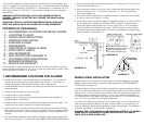
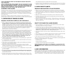
2. To insure aesthetic alignment of the alarm with the hallway or wall, the “A” line on the
mounting plate must be parallel with the hallway when ceiling mounting or horizontal
when wall mounting.
3. After selecting the proper smoke alarm location as described in Section 1, attach the
mounting plate to the ceiling as shown in Figure 1. For wall mounting see Figure 2.
Place mounting plate on the wall. Be sure the “UP FOR WALL MOUNTING “ text
FIGURE 1 FIGURE 2
FIGURE 3 FIGURE 4
When mounting
in a hallway, the
“A” line should
be parallel with
the hallway.
When wall mounting,
the “A” line should
be horizontal and
the “UP FOR WALL
MOUNTING” arrow
must be pointing up.
Alignment Marks
Install
Remove