1.PlaceboilerintheselecledIocalion(asnearchimneyaspossible.)Your
boilerisshippedassembled.YouneedonlyIoinsfalltheReliefValveand
adrainlineto carryanywalerorsteamIo adrain.
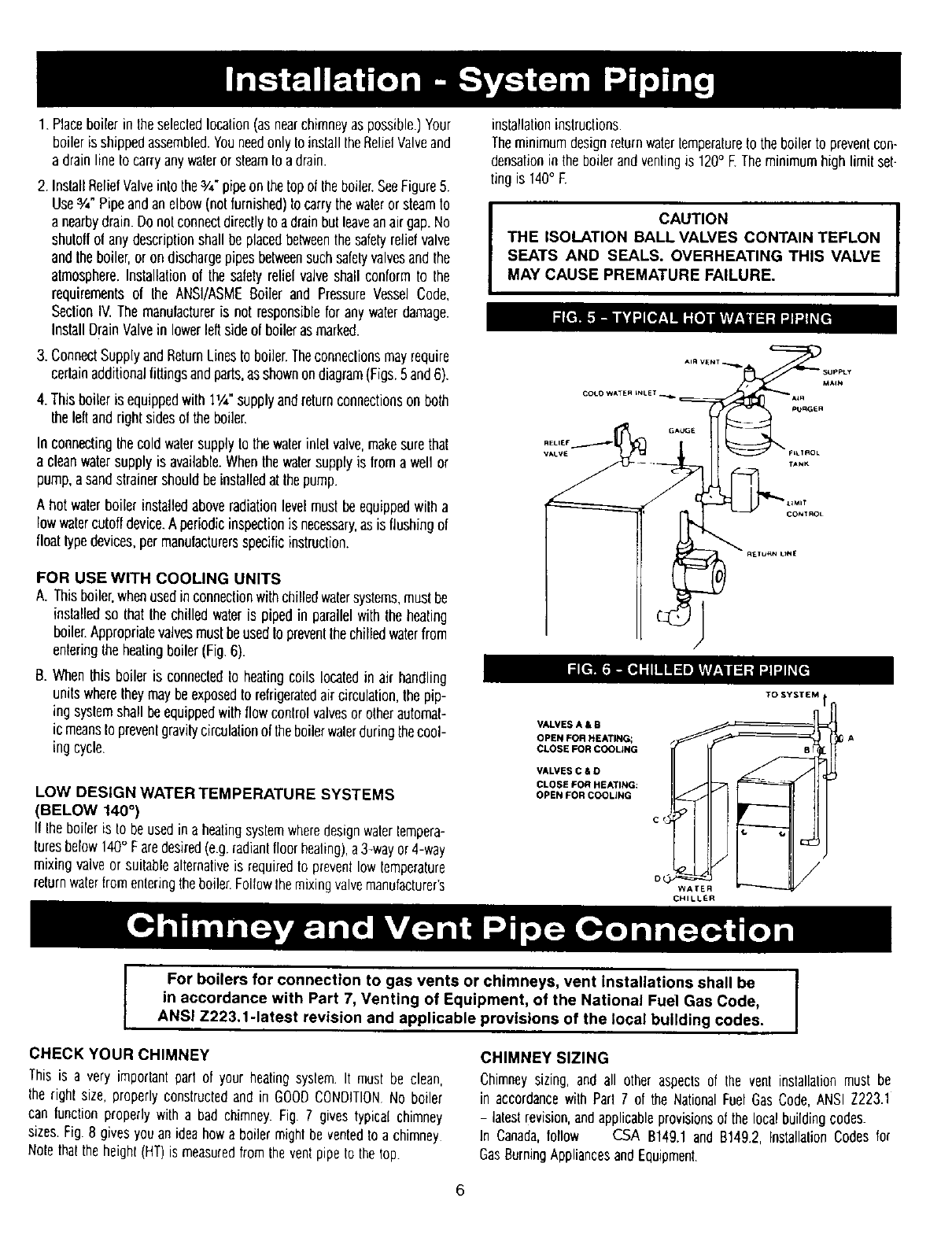
2. InstallRelielValveinto the3/,,-pipeonthetopol Iheboiler.SeeFigure5.
Use¾" Pipeandanelbow(nolfurnished)to carrythewalerorsteamto
anearbydrain.Donotconnectdirectlytoadrainbulleaveanairgap.No
shutollol anydescriptionshallbeplacedbetweenthesafdy rebelvalve
andtheboiler,or ondischargepipesbetweensuchsafetyvalvesandthe
atmosphere.Installationol thesafetyrelielvalveshall conformto the
requirementsof the ANSI/ASMEBoiler and PressureVesselCode,
SeclionIV.Themanulactureris not responsiblefor any waterdamage.
InstallDrainValvein lowerleftsideof boilerasmarked.
3. ConnectSupplyandReturnLinesto boiler.Theconneclionsmayrequire
certainadditionalfiltingsandparts,as shownondiagram(Figs.5and6).
4. Thisboileris equippedwilh 11/4"supplyandreturnconnectionsonboth
theleftandrightsidesol theboiler.
In connectingthecoldwatersupplytothewalerinlelvalve,makesurethat
a cleanwalersupplyis available.Whenthewatersupplyis froma weftor
pump,asandstrainershouldbeinstalledat thepump.
A hotwalerboiler installedaboveradiationlevelmustbeequippedwilh a
lowwatercutoffdevice.A periodicinspectionis necessary,as is flushingof
floattypedevices,permanufacturersspecificinstruction.
FOR USE WITH COOUNG UNITS
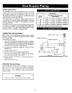
A. Thisboiler,whenusedinconnectionwithchilledwatersystems,mustbe
installedso that thechilled wateris pipedin parallelwiththeheating
boiler.Appropriatevalvesmustbeused1oprevenlthechilledwaterfrom
enteringtheheatingboiler(Fig.6).
B. Whenthisboiler is connectedto heatingcoils locatedin air handling
unitswheretheymaybeexposedto refrigeratedaircirculation,thepip-
ing syslemshallbeequippedwithflowcontrolvalvesorotherautomaf-
ic meansto prevenlgravgycirculationof theboilerwalerduringthecool-
ing cycle.
LOW DESIGN WATER TEMPERATURE SYSTEMS
(BELOW 140°)
If Iheboileris to beusedin aheatingsysfemwheredesignwaterlempera-
luresbelow140° Faredesired(e.g.radianlfloorhealing),a3-wayor4-way
mixingvalveor suitablealternativeis requiredto preventlowfemperature
returnwaterfromenleringtheboiler.FollowIhemixingvalvemanufacturer's
installationinstructions.
TheminimumdesignreturnwaterLemperatureIo theboilerto prevenlcon-
densationin theboilerandventingis 120° E Theminimumhigh limil set-
ting is 140° F.
I CAUTION
THE ISOLATION BALL VALVES CONTAIN TEFLON
SEATS AND SEALS. OVERHEATING THIS VALVE
MAY CAUSE PREMATURE FAILURE.
COt.o WATE_ LNLET.
VALVES A & B
OPEN FOR HEATING;
CLOSE FOR COOLING
VALVES C &O
CLOSE FOR HEATING:
OPEN FOR COOLING
TO SYSTEM
c d
WAFER
CHILLER
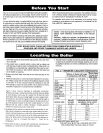
For boilers for connection to gas vents or chimneys, vent Installations shall be
in accordance with Part 7, Venting of Equipment, of the National Fue| Gas Code,
ANSI Z223.1-1atest revision and applicable provisions of the local building codes.
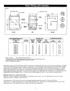
CHIMNEY SIZING
CHECK YOUR CHIMNEY
Thisis a very imporfantpart of your heatingsystem It mustbe clean,
theright size, properlyconstructedandin GOODCONDITIONNo boiler
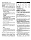
can lunctionproperlywith a bad chimney.Fig. 7 givestypical chimney
sizes.Fig.8 givesyouanideahowa boilermightbe ventedto achimney
Nofetha_theheight(HT)is measuredfromtheventpipeto the lop.
Chimneysizing, and all other aspectsof the vent installationmust be
in accordancewith Part7 of the NationalFuelGasCode,ANSIZ223.1
- laleslrevision,andapplicableprovisionsof the localbuildingcodes.
In Canada,follow CSA B149.1and B149.2,InstallabonCodesfor
GasBurningAppliancesandEquipment.
6


