


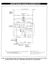
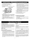
PWX WITH STANDING PILOT:
Thermostat calls for heat, completing the circuit to the aquastat and gas valve. The sequence is as follows: The
LED light indicating a call for heat and circulator, in the control panel, will illuminate. The automatic vent damper
will begin to open. When the vent damper is completely open and the end switches are made, the gas valve /
burner LED light will illuminate and the main valve will open, lighting all the burners. The burners will continue to
fire until either the thermostat or high limit, in the aquastat, is satisfied. If the high limit is satisfied and a call for
heat remains from the thermostat, the main valve will close, shutting off gas supply to the burners and the
associated LED light in the control panel. The circulator will continue to operate and circulator LED light will
remain on until the thermostat is satisfied.
Please note the main power LED light, in the control panel, will remain on until line voltage to the boiler is turned
off or disconnected.
1.
2,
3,
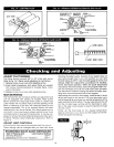
INITIAL SERVICE CHECKS
BEFORE TROUBLESHOOTING:
A. MAKE SURE THAT CIRCUIT BREAKER IS ON OR FUSE IS OK AT ELECTRICAL PANEL.
B. MAKE SURE THAT SERVICE SWITCH IS ON.
C. MAKE SURE THAT GAS IS ON AT THE GAS METER, AND THAT ALL APPROPRIATE MANUAL
SHUTOFF VALVES AND GAS CONTROL VALVE ARE OPEN.
D. MAKE SURE THAT THE THERMOSTAT IS CALLING FOR HEAT.
E. CHECK THAT WIRE CONNECTORS AT THE L7148F CONTROL, TRANSFORMER AND $8600 CONTROL
(IF USED) ARE SECURELY PLUGGED IN OR CONNECTED.
TROUBLESHOOTING TOOLS:
A. VOLTMETER TO CHECK 120 VAC AND 24 VAC.
B. CONTINUITY TESTER.
C. U-TUBE MANOMETER OR DIFFERENTIAL PRESSUREGAUGE WITH 0-14" RANGE(0.1" SCALE) FOR
MEASURING INLET AND MANIFOLD GAS PRESSURES.
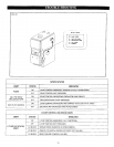
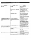
WHAT IS SYSTEM STATUS ?
A. CONSULT THE CHART ON THE FOLLOWING PAGE.
B. FIGURE 19 ON PAGE 25 SHOWS THE LOCATION ON THE BOILER OF THE SYSTEM STATUS LIGHTS.
24