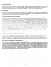
pmI[$|U_{ R[e.ll_l I,_I_TO_I ¢ONVENIENCI_ WIRING
ADN_TMENY TERMKNA_,_(31 T[ RMr NAL3 (2)
tUNO_m CAP $CA( (OPTIONAL) _T L(T _'R[SSUP £
o+
yH [,_MO¢OuPt-E @1LOT AD$_ITM[NT
¢ONNI;C_' K)N IUND[R €.AP It AIW_
lUTTON ¢ONTRO_A_VI_
PRF._SVR E REGUL_,TOR
ADJUSTMENT
(IJNDI[R +CAp SCR[W
I*IIF.SSI#RE TA
INf.(7
WIRING
TtRMIII/_..513)
T_ L(I" _SU R[
YIIRMI_(21
11._ L_ERCAP SCRElW|
_G_S
€O_TROS.
f OUTER MANTEL
,..:..:--.:...-:..:..:,
I111; + +':'+' ':'+1
_SHARP INNERCONES
ADJUST PILOT BURNER
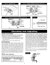
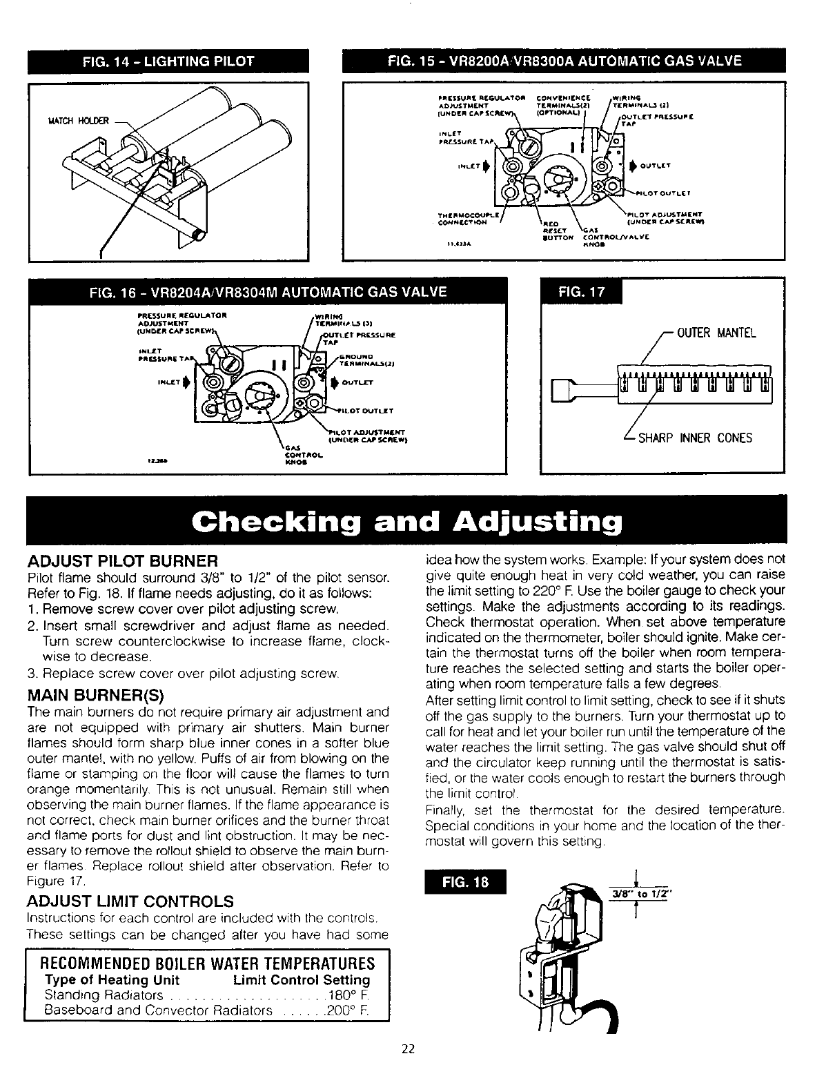
Pilot flame should surround 3/8" to 1/2" of the pilot sensor.
Refer to Fig. 18. If flame needs adjusting, do itas follows:
1. Remove screw cover over pilot adjusting screw.
2. Insert small screwdriver and adjust flame as needed.
Turn screw counterclockwise to increase flame, clock+
wise to decrease.
3. Replace screw cover over pilot adjusting screw.
MAIN BURNER(S)
The main burners do not require primary air adjustment and
are not equipped with primary air shutters Main burner
flames should form sharp blue inner cones in a softer blue
outer mantef, with no yellow. Puffs of air from blowing on the
flame or stamping on the floor wilt cause the flames to turn
orange momentarily This is not unusual. Remain still when
observing the main burner flames. If the flame appearance is
not correct, check main burner orifices and the burner throat
and flame ports for dust and lint obstruction. It may be nec-
essary to remove the rollout shield to observe the main burn-
er flames Replace rollout shield after observation Refer to
Figure 17+
ADJUST LIMIT CONTROLS
Instructions for each control are included with the controls
These settings can be changed after you have had some
RECOMMENDED BOILERWATER TEMPERATURES J
Type of Heating Unit Limit Control Setting
I
Standing Radiators .................... 180° F.
Baseboard and Convector Radiators ...... 200 ° F.
idea how the system works. Example: If your system does not
give quite enough heat in very cold weather, you can raise
the limit setting to 220° R Use the boiler gauge to check your
settings. Make the adjustments according to its readings.
Check thermostat operation. When set above temperature
indicated on the thermometer, boiler should ignite. Make cer-
tain the thermostat turns off the boiler when room tempera-
ture reaches the selected setting and starts the boiler oper-
ating when room temperature falls a few degrees.
After setting limit control to limit setting, check to see if it shuts
off the gas supply to the burners. Turn your thermostat up to
call for heat and let your boiler run until the temperature of the
water reaches the limit setting. The gas valve should shut off
and the circulator keep running until the thermostat is satis-
fied, or the water cools enough to restart the burners through
the limit control
FinaPly, set the thermostat for the desired temperature.
Special conditions in your home and the location of the ther-
mostat will govern this setting
3/8" to 1/2"'
22


