


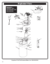
36
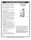
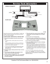
Service Tech Information
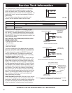
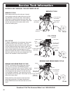
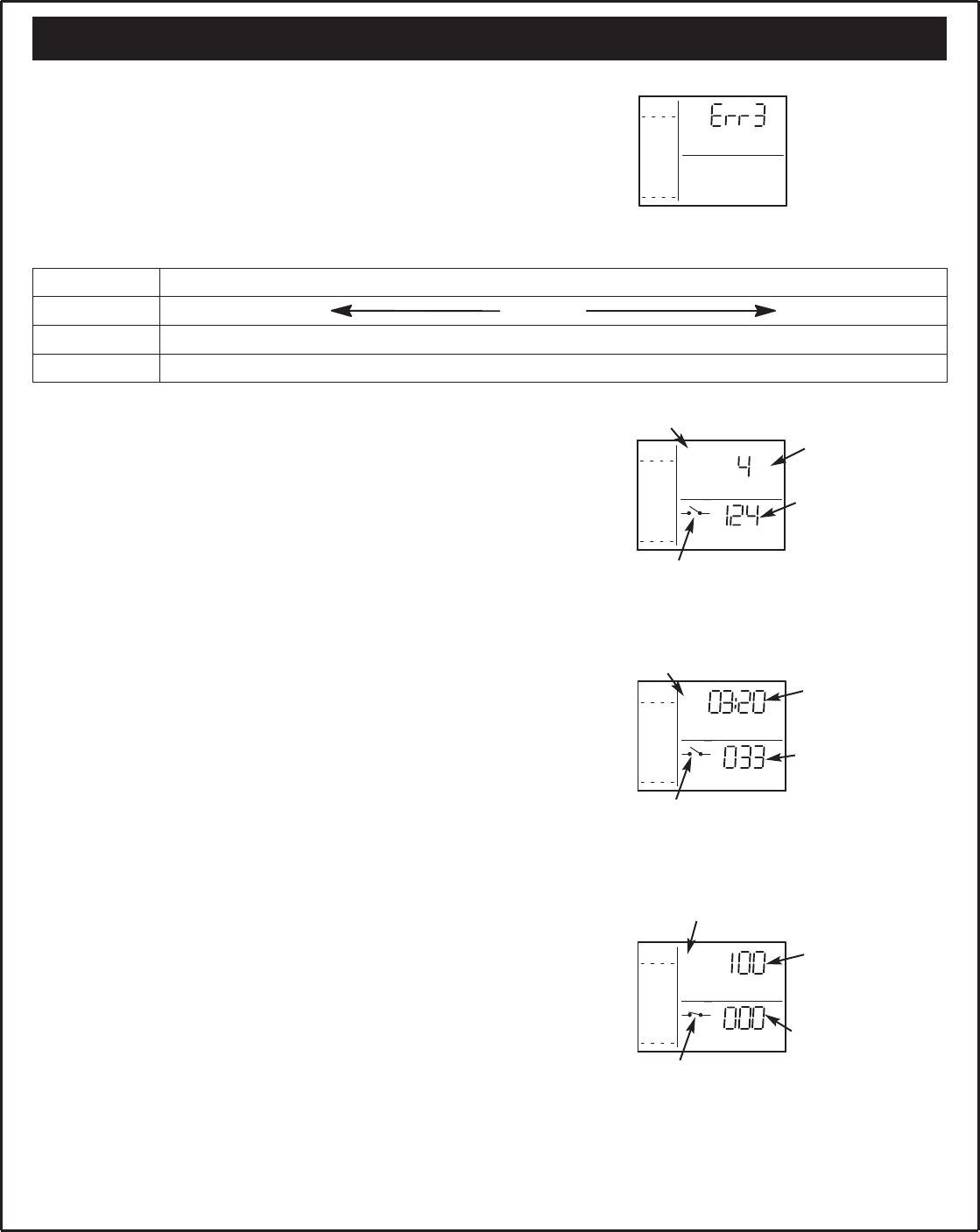
FIG. 60
The faceplate timer (PWA) computer has a self-diag-
nostic function for the electrical system, except put
power and water meter. The computer monitors elec-
tronic components and circuits for correct operation. If a
malfunction occurs, an error code appears in the face-
plate display.
The chart below shows the error codes that could
appear, and the possible defects for each code.
While an error code appears in the display, all face
plate buttons are inoperable except the SELECT1 but-
ton. SELECT1 remains operational so the service per-
son can make the MANUAL INITIATED ELECTRONIC
DIAGNOSTICS (below) to further isolate the defect, and
check the water meter.
PROCEDURE FOR REMOVING ERROR CODE
FROM FACEPLATE:
• Unplug transformer from outlet.
• Correct defect
• Plug in transformer.
• Wait for 8 minutes.
The error code will return if the defect was not corrected.
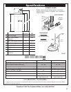
MANUAL INITIATED ELECTRONICS DIAGNOSTICS:
To enter diagnostics, press the SELECT1 button and
hold for three seconds. The display will show valve
cycle position, position switch status (open or closed),
and turbine operation. See Fig. 59.
TURBINE OPERATION: If no water is flowing through
the softener, the turbine indicator displays three zeros.
When water is flowing, the flow bar scrolls across the
display, and a 000 to 140 count repeats for each gallon
of water passing through the turbine. To check for posi-
tive operation of the turbine if zeros are shown, open a
nearby soft water faucet and observe the turbine count
and flow bar. If you don’t get a reading in the display,
with faucet open, pull the sensor from the valve outlet
port. Pass a small magnet back and forth in front of the
sensor. You should get a reading in the display. If you
get a reading, unhook the in and out plumbing and
check the turbine for binding.
POSITION SWITCH STATUS: With the valve in service,
or any of the recharge cycles, the switch indicator will
show open, while the valve is rotating from one position
to another, the indicator will show the switch closed. A
defect is probable if indications vary from this pattern.
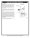
SALT
LEVEL
SIGNAL
LEVEL
8
7
6
5
4
3
2
1
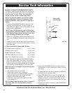
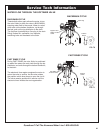
FIG. 61
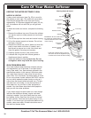
SALT
LEVEL
SIGNAL
LEVEL
8
7
6
5
4
3
2
1
FLOW RATE
DAY
SERV
SALT
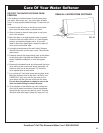
LEVEL
SIGNAL
LEVEL
8
7
6
5
4
3
2
1
FLOW RATE
FILL
TIME REMAINING
SALT
LEVEL
SIGNAL
LEVEL
8
7
6
5
4
3
2
1
FLOW RATE
FILL
BRINE
TIME REMAINING
valve position indicator
VALVE IN SERVICE POSITION
VALVE IN RECHARGE POSITION (FILL, IN THIS EXAMPLE)
VALVE ROTATING FROM ONE RECHARGE POSITION TO ANOTHER
(FROM FILL TO BRINEING IN THIS EXAMPLE)
number of days
since the last
regeneration
minutes of fill
cycle remaining
position switch
indicator (open)
water meter
turbine count
water meter
turbine count
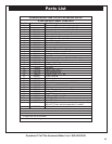
Questions? Call The Kenmore Water Line 1-800-426-9345
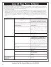
POSSIBLE DEFECT
CODE MOST LIKELY LESS LIKELY
Err1, Err3, Err4 motor inoperative / wiring harness or connection to switch / position switch . valve defect causing high torque
Err5 faceplate timer (PWA)
valve position indicator
(Fill and Brine Flashing)
valve position indicator
position switch
indicator (open)
position switch
indicator (closed)
minutes of brining
time (begins to count
down when valve
reaches brining
position)
water meter
turbine count