


A.Toolsrequired:
1. T15TorxScrewdriver
5. Removethetorxscrewlocatedbesidethepilottubeonthe
lowerfrontof thegasvalveassemblywitha T15torx
screwdriver.
2. 3/16"slottedscrewdriver.
3. Open-endwrenches7/16",and3/4".
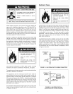
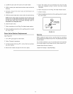
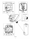
Fortheseinstructions, please see Figure 28.
B. Removing Electronic Control Module:
1. Turn the gas control/temperature knob to the "OFF" position.
2. Turn offthe gas at the manual shut-offvalve on the gas supply
line.
3. Disconnect the wire connectors from the piezo igniter, tank
sensors, and thermopile mounted on the lower front of the
gas control valve assembly.
6. Depress the two plastic locking tabs on lower front surface of
gas valve with a 3/16" slotted screwdriver.
7. Grasp the sides of the gas valve and pull outward to remove.
D. Removing Gas Valve Backplate:
1. Follow steps 1 to 7 in C above to remove the gas valve assembly.
2. Pull forward or break off the two plastic locking tabs using a
3/16" slotted screwdriver.
3. Grasp the sides of the back-plate and slide upward to remove
it from the gas valve nipple.
E: installing Gas Valve Assembly:
4. Remove the torx screw located beside the pilot tube on the
lower front of the electronic control module with a T15 torx
screwdriver.
1. Install the new gas valve (with back-plate) on the tank nipple
by sliding the assembly downward until the locking tabs are
fully engaged.
5. Depress the two plastic locking tabs on the top surface of
the electronic control module with a 3/16" slotted
screwdriver.
6. Grasp the sides of the electronic control module and pull
outward to remove.
C. Removing Gas Valve Assembly:
1. Follow steps 1 to 6 in B above to remove the electronic control
module.
2. Disconnect the inlet gas supply to the gas valve.
3. Loosen the flare nut that connects the pilot tube to the bottom
of the gas control valve assembly with a 7/16" open-end
wrench. Pull down on the pilot tube to separate the tube from
the gas valve.
4. Loosen the flange nut that connects the burner tube to bottom
of gas control valve with a 3/4" open-end wrench. Pull down
on the burner tube to separate the tube from the gas valve.
F:
1.
4.
Insure the gas valve is securely locked before proceeding to
next step.
Reconnect the burner tube, pilot tube, and inlet gas supply
line to the gas valve. Tighten securely and check for gas leaks.
installing Electronic Control Module:
Align the two plastic locking tabs on the top surface of the
electronic control module with the openings of the gas valve
back-plate. Press on the front of the control module until it
locks into position.
Reinstall the torx screw on the lower front of the electronic
control module (beside pilot tube) with a T15 torx screwdriver.
Tighten securely.
Reconnect the wire connectors from the piezo igniter, tank
sensors, and thermopile to the electronic control module.
Light the heater following the lighting and operating
instructions on the front surface of the heater.
26