


NOTE:Toprotectagainstuntimelycorrosionofhot and cold
water fittings, it is strongly recommended that di=electric
unions or couplings be installed on this water heater when
connected to copper pipe.
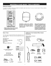
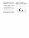
1. Look at the top cover of the water heater. The hot water outlet
is marked hot. Put two or three turns of teflon tape around
the threaded end of the threaded-to-sweat coupling and
around both ends of the 3/4" threaded nipple. Using flexible
connectors, connect the hot water pipe to the hot water outlet
of the water heater.
2. Look at the top cover of the water heater. The cold water inlet
is marked cold. Put two or three turns of teflon tape around
the threaded end of the threaded-to-sweat coupling and
around both ends of the 3/4" threaded nipple. Using flexible
connectors, connect the cold water pipe to the cold water
inlet of the water heater.
NOTE: Your water heater is insulated to minimize heat loss
from the tank. Further reduction in heat loss can be
accomplished by insulating the hot water lines from the
water heater.
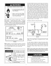
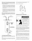
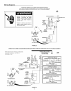
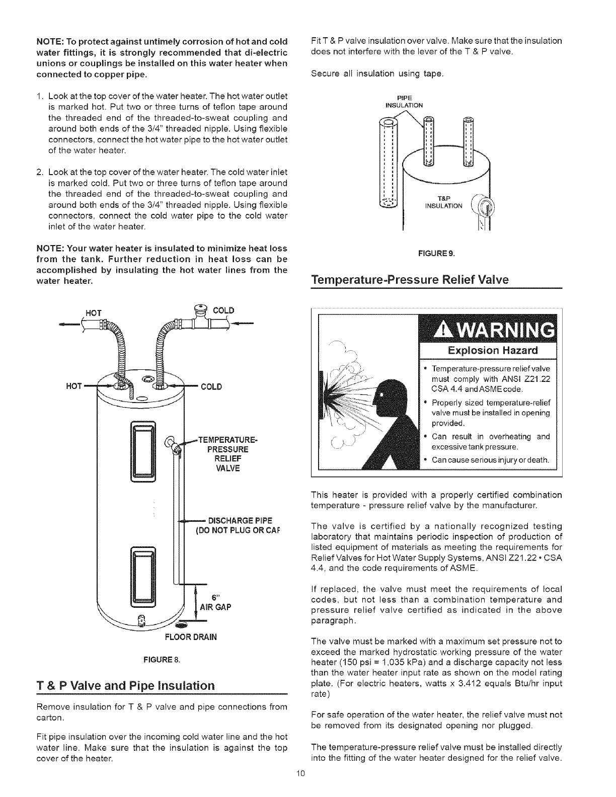
HOT g COD
HOTm_ _mCOLD
PRESSURE
RELIEF
VALVE
PIPE
(DO NOT PLUG OR CAF
AiR GAP
FLOOR DRAIN
FIGURE 8.
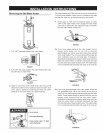
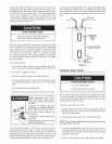
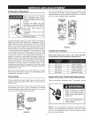
T & P Valve and Pipe insulation
Remove insulation for T & P valve and pipe connections from
carton.
Fit pipe insulation over the incoming cold water line and the hot
water line. Make sure that the insulation is against the top
cover of the heater.
Fit T & P valve insulation over valve. Make sure that the insulation
does not interfere with the lever of the T & P valve.
Secure all insulation using tape.
FIGURE 9.
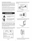
Temperature=Pressure Relief Valve
i
Explosion Hazard
"Tem perature-pressure relief valve
must comply with ANSI Z21.22
CSA 4.4 andASMEcode.
Properly sized temperature-relief
valve must be installed inopening
provided.
" Can result in overheating and
excessive tank pressure.
• Can cause serious injury or death.
10
This heater is provided with a properly certified combination
temperature - pressure relief valve by the manufacturer.
The valve is certified by a nationally recognized testing
laboratory that maintains periodic inspection of production of
listed equipment of materials as meeting the requirements for
Relief Valves for Hot Water Supply Systems, ANSI Z21.22 • CSA
4.4, and the code requirements of ASME.
If replaced, the valve must meet the requirements of local
codes, but not less than a combination temperature and
pressure relief valve certified as indicated in the above
paragraph.
The valve must be marked with a maximum set pressure not to
exceed the marked hydrostatic working pressure of the water
heater (150 psi = 1,035 kPa) and a discharge capacity not less
than the water heater input rate as shown on the model rating
plate. (For electric heaters, watts x 3.412 equals Btu/hr input
rate)
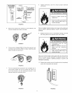
For safe operation of the water heater, the relief valve must not
be removed from its designated opening nor plugged.
The temperature-pressure relief valve must be installed directly
into the fitting of the water heater designed for the relief valve.