


17
The appliance and its gas connection must be leak tested before
placing the appliance in operation.
The appliance and its individual shutoff valve shall be
disconnected from the gas supply piping system during any
pressure testing of that system at test pressures in excess of
1/2 pound per square inch (3.5kPa). It shall be isolated from
the gas supply piping system by closing its individual manual
shutoff valve during any pressure testing of the gas supply piping
system at test pressures equal to or less than 1/2 pound per
square inch (3.5kPa).
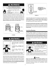
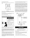
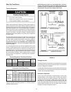
Connecting the gas piping to the gas control valve of the water
heater can be accomplished by either of the two methods shown
in Figures 19 and 20.
There must be:
• A readily accessible manual shut off valve in the gas supply
line serving the water heater, and
• A drip leg (sediment trap) ahead of the gas control valve to
help prevent dirt and foreign materials from entering the gas
control valve.
• A fl exible gas connector or a ground joint union between
the shut off valve and control valve to permit servicing of the
unit.
Be sure to check all the gas piping for leaks before lighting the
water heater. Use a soapy water solution, not a match or open
fl ame. Rinse off soapy solution and wipe dry.
The minimum inlet gas pressure shown on the rating plate is that
which will permit fi ring at the rated input.
Water heaters covered in this manual have been tested and
approved for installation at elevations up to 7,700 feet (2,347m)
above sea level. For installation above 7,700 feet (2,347m),
the water heater’s Btu input should be reduced at the rate of
4 percent for each 1,000 feet (305 m) above sea level which
requires replacement of the burner orifi ce in accordance with the
National Fuel Gas Code ANSI Z223.1/NFPA 54. Contact your
local gas supplier for further information.
Failure to replace the standard orifi ce with the proper high
altitude orifi ce when installed at elevations above 7,700 feet
(2,347m) could result in improper and ineffi cient operation of
the appliance, producing carbon monoxide gas in excess of the
safe limits. This could result in serious injury or death. Contact
your local gas supplier for any specifi c changes that may be
required in your area.
Use pipe joint compound or tefl on tape marked as being
resistant to the action of petroleum (Propane [L.P.]) gases.
Sediment Traps
Contaminants in the gas lines may cause improper operation
of the gas control valve that may result in fi re or explosion.
Before attaching the gas line be sure that all gas pipe is clean
on the inside. To trap any dirt or foreign material in the gas
supply line, a drip leg (sometimes called a sediment trap) must
be incorporated in the piping. The drip leg must be readily
accessible. Install in accordance with the Gas Piping section.
Refer to the current edition of th
e National Fuel Gas Code,
ANSI Z223.1/NFPA 54.
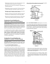
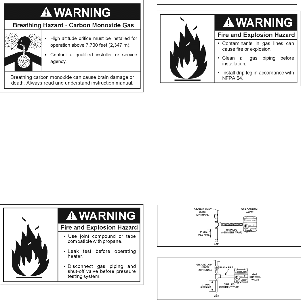
A sediment trap shall be installed as close to the inlet of the water
heater as practical at the time of water heater installation. The
sediment trap shall be either a tee fi tting with a capped nipple
in the bottom outlet or other device recognized as an effective
sediment trap. If a tee fi tting is used, it shall be installed in
conformance with one of the methods of installation, shown in
Figures 19 and 20.
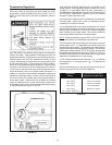
FIGURE 19. GAS PIPING WITH FLEXIBLE CONNECTOR.
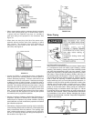
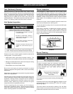
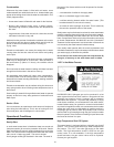
FIGURE 20. GAS PIPING WITH ALL BLACK IRON PIPE TO
GAS CONTROL.