


30
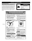
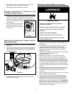
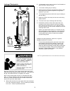
Replacing the Flame Sense/Hot Surface igniter
Assembly
1. Remove the manifold/burner assembly. See Removing the
Manifold/Burner Assembly.
2. Lift the retainer clip straight up from the back of the manifold
component block (using a flat-blade screwdriver), then
remove the manifold component block from the manifold
door (Figure 37.)
3. Remove and keep the screw securing the flame sense/hot
surface igniter assembly (Figure 37)
4. Remove and discard the old flame sense/hot surface igniter
assembly.
5. Route the new flame sense/hot surface igniter connector
wire through manifold/burner door opening as shown in
figure 37. Secure assembly to bracket using screw removed
earlier.
FIGURE 37.
Screw
Retainer Clip
Manifold Component
Block
Flame Sense/
Hot Surface
Igniter Assembly
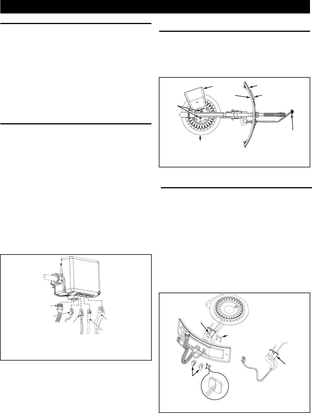
Removing the Burner from the Manifold/
Burner Assembly
Natural Gas Burner
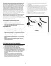
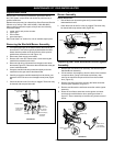
1. Take off the burner by removing the two (2) screws located
underneath the burner.
2. Check the burner to see if it is dirty or clogged. The burner may
be cleaned with soap and hot water (Figure 36).
Replacement Parts
IMPORTANT: The following maintenance procedures are for
the FVIR System components and should be performed by a
qualified technician.
Replacement parts may be ordered from Sears Parts and Service
Centers or by calling 1-800-4-MY-HOME (1-800-469-4663).
When ordering replacement parts, always have the following
information ready:
1. model, serial, and product number
2. type of gas
3. item number
4. parts description
See “Parts Order List” section for a list of available repair parts.
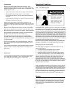
Removing the Manifold/Burner Assembly
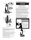
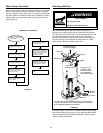
1. Turn off the gas supply to the water heater at the manual gas
shut-off valve. This valve is typically located beside the water
heater. Note the position of the shut-off valve in the open/on
position then proceed to turn it off (Figure 12).
2. Disconnect power supply to the heater.
3. Remove the outer door. Remove the 2 screw securing the
manifold door assembly to the skirt.
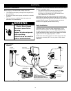
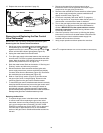
4. Disconnect all wiring connectors from the gas control valve/
thermostat (Figure 35). Disconnect the manifold tube at the gas
control valve/thermostat.
5. Grasp the manifold tube and push down slightly to free the
manifold from the gas control valve/thermostat.
6. Carefully remove the manifold assembly from the burner com-
partment. NOTE: Be sure not to damage internal parts (Figure
39).
7. Check the burner to see if it is dirty or clogged. The burner may
be cleaned with soap and hot water.
MAINTENANCE OF YOUR WATER HEATER
Burner
(Bottom View)
Screws
Manifold Door Assembly
Igniter/Flame
Sense Connector
View Port
Scoop side to be
on the same side
as View Port
FIGURE 36.
Manifold Tube
Control Display,
Anode Rod
Connector
Pressure
Switch / Fan,
FV Sensor
Connector
Power Supply
Transformer
Connector
Igniter/Flame
Sense
Connector
Gas Control Valve/
Thermostat
FIGURE 35.