


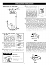
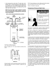
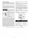

Lookatthetopofthewaterheater.Thecoldwaterinletis
marked"COLD".Puttwoorthreeturnsofteflontapearound
thethreadedendofthethreaded-to-sweatcouplingand
aroundbothendsofthe3/4"NPTthreadednipple.Using
flexibleconnectors,connectthecoldwaterpipetothecold
waterinletofthewaterheater.
NOTE: This water heater is super insulated to minimize
heat loss from the tank. Further reduction in heat loss
can be accomplished by insulating the hot water lines
from the water heater.
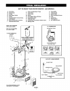
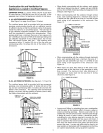
INSTALLATION COMPLETED USING INSTALLATION KIT
FLEXIBLE
WATER
CONNECTORS
NOT WATER
COLD WATER
OUTLET INLET
t t SHUTOFF
VALVE
THREADED TO THREADED TO
SWEAT COUPLING SWEAT COUPLING
3/4"THREADED _
HEAT TRAP WITH _ "41""""""- 314"THREADED
SECONDARY COUPLING/HEAT TRAP
ANODE
DRAFTHOOD
TEMPERATURE-
_PRESSURE
RELIEF VALVE
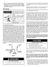
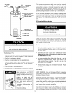
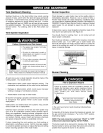
Fit T & Pvalve insulation over valve. Make sure that the insulation
does not interfere with the lever of the T & P valve.
Secure all insulation using tape.
Temperature-Pressure Relief Valve
/
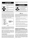
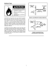
Explosion Hazard
• Temperature-pressure relief valve
must comply with ANSI Z21.22
and ASME code.
• Properly sized temperature-
pressure relief valve must be
installed in opening provided.
• Can result in overheating and
excessive tank pressure.
• Can cause serious injury or death.
This heater is provided with a properly certified combination
temperature - pressure relief valve by the manufacturer.
The valve is certified by a nationally recognized testing
laboratory that maintains periodic inspection of production of
listed equipment of materials as meeting the requirements for
Relief Valves and Automatic Gas Shutoff Devices for Hot Water
Supply Systems, ANSI Z21.22 and the code requirements of
ASME.
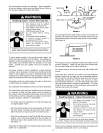
DISCHARGE PIPE
(Do not cap or plug)
FLOORDRAIN
FIGURE 15.
T & P Valve and Pipe Insulation
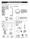
Remove insulation for T & P valve and pipe connections from
carton.
PIPE
INSULATION FLUEPIPE
T&P )
RGURE 15A.
Fit pipe insulation over the incoming cold water line and the hot
water line. Make sure that the insulation is against the top
cover of the heater.
13
If replaced, the valve must meet the requirements of local codes,
but not less than a combination temperature and pressure
relief valve certified as indicated in the above paragraph.
The valve must be marked with a maximum set pressure not to
exceed the marked hydrostatic working pressure of the water
heater (150 psi = 1,035 kPa) and a discharge capacity not less
than the water heater input rate as shown on the model rating
plate.
For safe operation of the water heater, the relief valve must not
be removed from its designated opening nor plugged.
The temperature-pressure relief valve must be installed directly
into the fitting of the water heater designed for the relief valve.
Position the valve downward and provide tubing so that any
discharge will exit only within 6 inches (153 mm) above, or at
any distance below the structural floor, see Figure 16. Be certain
that no contact is made with any live electrical part. The
discharge opening must not be blocked or reduced in size
under any circumstances. Excessive length, over 30 feet
(9.14 m), or use of more than four elbows can cause restriction
and reduce the discharge capacity of the valve.
No valve or other obstruction is to be placed between the relief
valve and the tank. Do not connect tubing directly to discharge
drain unless a 6 inch air gap is provided. To prevent bodily
injury, hazard to life, or property damage, the relief valve must
be allowed to discharge water in quantities should
circumstances demand. If the discharge pipe is not connected
to a drain or other suitable means, the water flow may cause
property damage.