


Installation Instructions (cont'd)
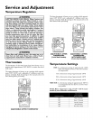
Temperature-Pressure
Relief Valve
_,WARNING
At the time of manufacture this water heater was provided
with a combination temperature-pressuras relief valve cer-
tiffed by a nationally recognized testing laboratory that
maintains periodic inspection of production of listed equip-
ment or materials, as meeting the requirements for Relief
Valves and Automatic Gas Shutoff Devices for Hot Water
Supply Systems, and the current edition of ANSI Z21.22 ,
CSA 4.4 and the code requirements of ASHE. If replaced,
the valve must meet the requirements of local codes, but
not less than a combination temperature and pressure
relief valve certified as meeting the requirements for Relief
Valves and Automatic Gas Shutoff Devices for Hot Water
Supply Systems, ANSI Z21.22, CSA 4.4 by a nationally rec-
ognized testing laboratory that maintains periodic inspec-
tion of production of listed equipment or materials.
The valve must be marked with a maximum set pressure
not to exceed the marked hydrostatic working pressure of
the water heater (150 Ibs. p.s.i.) and a discharge capacity
not less than the water heater input rate as shown on the
model rating plate. (Electric heaters - watts divided by 1000
x 3412 equal BTU/Hr. rate.)
Your local jurisdictional authority, while mandating the use
of a temperature-pressure relief valve complying with ANSI
Z21.22, CSA 4.4 and ASME, may require a valve model dif-
ferent from the one furnished with the water heater.
Compliance with such local requirements must be satisfied
bythe installer or end user oftbe water heater with a local-
ly prescribed temperature-pressure relief valve installed in
the designated opening in the water heater in place of the
factory furnished valve.
For safe operation of the water heater, the relief valve must
not be removed from it's designated opening or plugged.
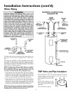
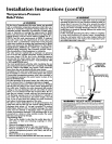
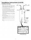
The temperature-pressure relief valve must be installed
directly into the fitting of the water heater designated for
the relief valve. Position the valve downward and provide
tubing so that any discharge will exit only within 6 inches
above, or at any distance below the structural floor. Be cer-
tain that no contact is made with any live electrical part.
The discharge opening must not be blocked or reduced in
size under any circumstances. Excessive length, over 30
feet, or use of more than four elbows can cause restriction
and reduce the discharge capacity of the valve.
No valve or other obstruction is to be placed between the
relief valve and the tank. Do not connect tubing directly to
discharge drain unless a 6" air gap is provided. To prevent
bodily injury, hazard to life, or property damage, the relief
valve must be allowed to discharge water in quantities
should circumstances demand. If the discharge pipe is not
connected to a drain or other suitable means, the water
flow may cause property damage.
The Discharge Pipe:
Must not be smaller in size than the outlet pipe size of
the valve, or have any reducing couplings or other
restriction.
Must not be plugged or blocked.
Must be of material listed for hot water distribution.
Must be installed so as to allow complete drainage of
both the temperature-pressure relief valve, and the dis-
charge pipe.
Must terminate at an adequate drain.
Must not haveany valve between the relief valve andtank.
&WARNING
The temperature-pressure relief valve must be manually
operated at leastoncea year.Caution shouldbe taken to
ensurethat (I) no one isin front of or around the outlet
of the temperature-pressure relief valve dischargeline,
and (2) the water manually dischargedwill not causeany
bodilyinjury or property damagebecausethe water may
be extremely hot.
If after manually operating the valve, it fails to complete-
ly reset and continues to release water, immediately,
closethe cold water inlet to the water heater, follow the
draining instructions,and replace the temperature-pres-
sure relief valvewith a new one.
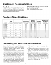
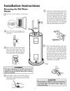
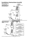
H_OT(
SHUT-OFF
VALVE
COLD
CONDUIT
__ PRESSURE
RELIEF VALVE
(Do not cap or plug)
6" AIR GAP
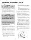
WARNING "RELIEF VALVE OPENING"
andthe codel_Ji_rnent_ OfASME
Compliance_th suchlocaliequilem_'_tsii_st besa_sf_,dbyth#instaHexolend_selofth_waterheatelw_h
a locally plescribe_JTempelature*Pl_ssureReliefValv_ installedinthe designated_ning in the watel
heater
• Ifa short shank (less than2") temperaltJle.plessurereltefvalveisto be installed
(_Sshown),_ nipple andcoupling mustbetJsed
• If_ long sha_k/2" or Io_ger) isto beinstalEed,do notuse thenippEea_d coupling
Aulomat_cGasShutoffDc_4cesfor Hot.WatclSupplySystems,ANSZ2122 bya nationallyrccognizeitcs_*
inglaboratory_hatmant_ns pcdodlcinspec_o_Ofproductionoilistedeq_prn_t ormatexialsThe valve
m_s_beodente_J,prov_ed_lh tubing,ol ot_er_se inst_ledsothatdischal_ecmqex_onlyw_hi_6 inches
above,Orata_ydis_anc_b_ow thes_ructuralflocl,andcannotcontactany I_veclcctrlcalpar[¸"
Fol safeopclat_onof_hcwa_elbeatel,_hcReliefVa_em_s_r_t be icmovedorpl_gecd
See mant_alhcadin_- =Temperat_rc*PiessuleReliefValve"fol installatJonand ma_n_enanc_oi Relief
Va_c, d_SChargc_ipeandothersafe_yprecat_ons
9