


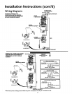
Installation Instructions (cont'd)
Temperature-Pressure
Relief Valve
_,WARNING
At the time of manufacture this water heater was provid-
ed with a combination temperature-pressuresrelief valve
certified bya nationally recognized testinglaboratory that
maintains periodic inspection of production of listed
equipment or materials, as meeting the requirements for
ReliefValvesand Automatic Gas ShutoffDevicesfor Hot
Water Supply Systems, and the latest edition of ANSI
Z21.22 and the code requirements of ASHE. If replaced,
the valvemust meet the requirements of local codes,but
not lessthan a combination temperature and pressure
relief valve certified as meeting the requirements for
ReliefValvesand Automatic Gas ShutoffDevicesfor Hot
Water SupplySystems,ANSI Z21.22 bya nationallyrecog-
nizedtestinglaboratory that maintainsperiodicinspection
ofproductionoflistedequipment or materials.
The valve must be marked with a maximum set pressure
not to exceedthe marked hydrostaticworkingpressureof
the water heater (150 Ibs./sq.in.) and a dischargecapacity
not lessthan the water heater input rate asshownon the
model rating plate. (Electric heaters - watts divided by
1000x 3415 equalBTU/Hr. rate.)
Yourlocaljurisdictionalauthority,while mandatingthe use
of a temperature-pressure relief valve complying with
ANSI Z21.22 and ASME, may require a valvemodel differ-
ent from the onefurnishedwith the water heater.
Compliance with such local requirements must be satis-
fied bythe installeror end userof the water heater with a
locally prescribed temperature-pressure relief valve
installedin the designatedopeningin the water heater in
daceofthe factory furnishedvalve.
For safe operation of the water heater, the relief valve
must not be removed from it's designated opening or
plugged.
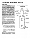
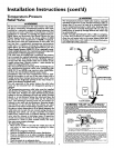
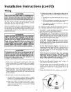
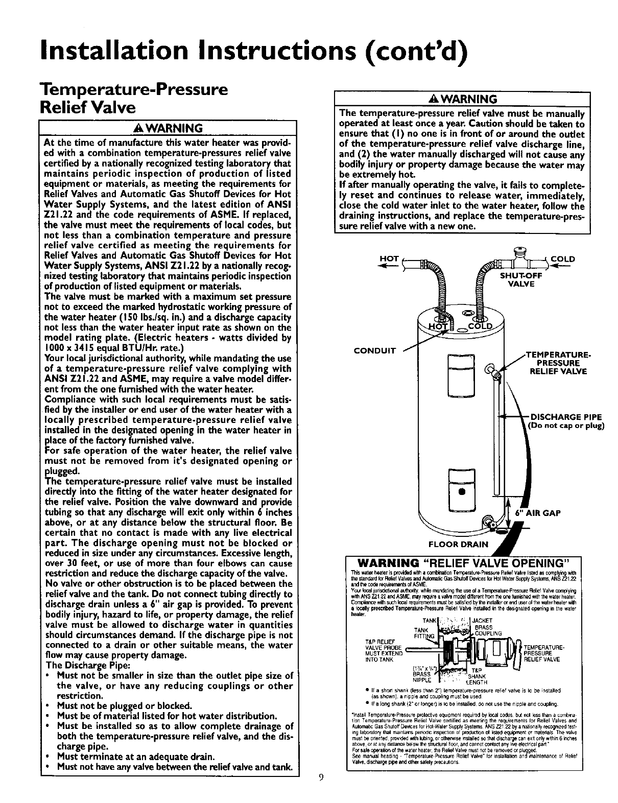
The temperature-pressure relief valve must be installed
directly into the fitting of the water heater designatedfor
the relief valve. Positionthe valve downwardand provide
tubing sothat anydischargewill exit onlywithin 6 inches
above, or at any distance below the structural floor. Be
certain that no contact is made with any live electrical
)art. The discharge opening must not be blocked or
reduced in sizeunder anycircumstances.Excessivelength,
over 30 feet, or use of more than four elbowscan cause
restriction and reduce the dischargecapacityofthe valve.
No valveor other obstructionisto be placedbetween the
relief valveandthe tank. Do not connecttubingdirectly to
dischargedrain unlessa 6" air gap isprovided.To prevent
bodilyinjury,hazard to life, or property damage,the relief
valve must be allowed to discharge water in quantities
shouldcircumstancesdemand. If the dischargepipeisnot
connectedto a drain or other suitable means, the water
flow may causepropertydamage.
The DischargePipe:
• Must not be smaller in sizethan the outlet pipe sizeof
the valve, or have any reducing couplings or other
restriction.
Must not bepluggedor blocked.
Mustbe ofmaterial listedfor hot water distribution.
Must be installedso as to allow complete drainage of
boththe temperature-pressurerelief valve,andthe dis-
chargepipe.
Mustterminate at anadequatedrain.
Mustnothaveanyvalvebetweenthe relief valveandtank.
• ,WARNING
The temperature-pressure relief valve must be manually
operated at leastonce a year.Caution shouldbe taken to
ensurethat (I) no one is in front of or around the outlet
of the temperature-pressure relief valve dischargeline,
and (2) the water manually dischargedwill not causeany
bodily injury or property damagebecausethe water may
beextremely hot.
If after manually operating the valve, it fails to complete-
ly reset and continues to release water, immediately,
close the cold water inlet to the water heater, follow the
draining instructions,and replace the temperature-pres-
surerelief valvewith a new one.
H_OT ( COLD
SHUT-OFF
VALVE
CONDUIT J
FLOOR DRAIN •
TEMPERATURE-
J PRESSURE
RELIEF VALVE
DISCHARGE PIPE
Do not cap or plug)
6" AIR GAP
r
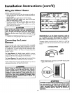
WARNING "RELIEF VALVE OPENING"
Thiswaterheaterisp_ovidedwilha co,_on Tempe_ Press_eRe_efValvelistedasco_plyingw_h
thestandardfo_RediQfValwsandAulomalicGasShutoffDewcesforH01WaterSupp_Systems,ANSZ2122
andthecoderequirementsofASME
Yc_'lc_ judsd_tl,0nalau_hontywhlern_ndatingtheuseofa Tempetatule-Pr_suleRelLefValve_¥rg
withANS72122andASME,may_Ie avah.emodeldlffelentPoretheonefurnished_ thewaterheater
Comp_ar_ewithsuchlocalrequirementsr_st be_ltisfbedbytheinslallerc_endt_el of thewaterheater_h
a legallyprescribedTempelalure-PteSsLJreRe[_elValveinstalledinthe designatedepe_ir,g inthe wafer
heate_
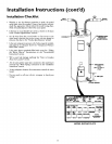
TANK : ' _ ; t, JACKET
, r_.,
TANK * 1" BRASS
FITTING COUPLING
VALVE PROBE TEMPERATURE-
MUST EX_rEND PRESSURE
iNTO TANK RELIEFVALVE
BRASS SHANK
• I1 ashort shank (less lhan 2") temperature-pressure reqief valve is Io be installe_J
(as shown}, anipple and coup_in9 must be used
• If a long shank (2" of loiter) is IO be in sla_led d<Jriot us_ the nipple end coupling
"Ins{all Tempetalure.Pre_ure prolective equipmenl _uir_ by local codes but nol less If,an acombine
lion Temperature-P,sssui8 RelicI Valve cetli{ied as meeting the requirernenls lot Reliel Valves and
Aulomauc Gas Shuloff De_,-_esforHot.Waler SupplySyslems ANS Z21 22by a helically recognized test.
rig labO_alory that r_ant ains peno_c ft_spectionof production o{lisle_ equipment el rnatehals The valve
mUSl he onenled provKled _th lubin9, or olhen_se i_slaJlodSOthat discUarge can exit only _thin 6inches
above¸ o, atany d_stancebelowIbe 5tnJcforel flOOr,and cannot contactany live electlica_ part
Forsafe operalio_ of the waterheatel, the Rehef Valve must not be iemoved or plugged¸
See maflua_ headirlg. "Temperah_re Pressure Relief Valve" {of il_slallatitl_ and mainlenance of Relief
Valve, discharg_ p_peand elher saletypr_autions