


872678-UIM-C-0213
4 Johnson Controls Unitary Products
PRECAUTIONS DURING BRAZING OF LINES
All outdoor unit and evaporator coil connections are copper-to-copper
and should be brazed with a phosphorous-copper alloy material such
as Silfos-5 or equivalent. DO NOT use soft solder. The outdoor units
have reusable service valves on both the liquid and vapor connections.
The total system refrigerant charge is retained within the outdoor unit
during shipping and installation. The reusable service valves are pro-
vided to evacuate and charge per this instruction.
Serious service problems can be avoided by taking adequate precau-
tions to assure an internally clean and dry system.
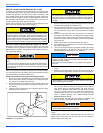
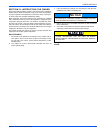
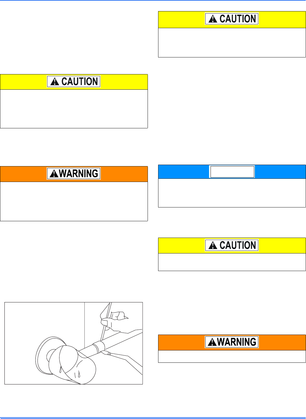
PRECAUTIONS DURING BRAZING SERVICE VALVE
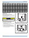
Precautions should be taken to prevent heat damage to service valve
by wrapping a wet rag around it as shown in Figure 4. Also, protect all
painted surfaces, insulation, and plastic base during brazing. After braz-
ing, cool joint with wet rag.
Valve can be opened by removing the plunger cap and fully inserting a
hex wrench into the stem and backing out counter-clockwise until valve
stem just touches the chamfered retaining wall.
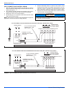
Connect the refrigerant lines using the following procedure:
1. Remove the cap and Schrader core from both the liquid and vapor
service valve service ports at the outdoor unit. Connect low pres-
sure nitrogen to the liquid line service port.
2. Braze the liquid line to the liquid valve at the outdoor unit. Be sure
to wrap the valve body with a wet rag. Allow the nitrogen to con-
tinue flowing.
3. Carefully remove the plugs from the evaporator liquid and vapor
connections at the indoor coil.
4. Braze the liquid line to the evaporator liquid connection. Nitrogen
should be flowing through the evaporator coil.
5. Slide the grommet away from the vapor connection at the indoor
coil. Braze the vapor line to the evaporator vapor connection. After
the connection has cooled, slide the grommet back into original
position.
6. Protect the vapor valve with a wet rag and braze the vapor line
connection to the outdoor unit. The nitrogen flow should be exiting
the system from the vapor service port connection. After this con-
nection has cooled, remove the nitrogen source from the liquid fit-
ting service port.
7. Replace the Schrader core in the liquid and vapor valves.
8. Go to SECTION IV or SECTION V for orifice or TXV installation
depending on application.
9. Leak test all refrigerant piping connections including the service
port flare caps to be sure they are leak tight. DO NOT OVER-
TIGHTEN (between 40 and 60 inch - lbs. maximum).
10. Evacuate the vapor line, evaporator, and liquid line to 500 microns
or less.
11. Replace cap on service ports. Do not remove the flare caps from
the service ports except when necessary for servicing the system.
12. Release the refrigerant charge into the system. Open both the liq-
uid and vapor valves by removing the plunger cap and with an
allen wrench back out counter-clockwise until valve stem just
touches the chamfered retaining wall. If the service valve is a ball
valve, use a cresent wrench to turn valve stem one-quater turn
counterclockwise to open. Do not overturn or the valve stem may
break or become damaged. See “PRECAUTIONS DURING
BRAZING SERVICE VALVE”.
13. Replace plunger cap finger tight, then tighten an additional 1/12
turn (1/2 hex flat). Cap must be replaced to prevent leaks.
See "System Charge” section for checking and recording system
charge.
Supplied with the outdoor unit is a Schrader Valve Core and Orifice for
highest sales volume indoor coil. The valve core must be installed in
equalizer fitting of the indoor coil.
Dry nitrogen should always be supplied through the tubing while it
is being brazed, because the temperature required is high enough
to cause oxidation of the copper unless an inert atmosphere is pro-
vided. The flow of dry nitrogen should continue until the joint has
cooled. Always use a pressure regulator and safety valve to insure
that only low pressure dry nitrogen is introduced into the tubing.
Only a small flow is necessary to displace air and prevent oxidation.
This is not a backseating valve. The service access port has a
valve core. Opening or closing valve does not close service access
port.
If the valve stem is backed out past the chamfered retaining wall,
the O-ring can be damaged causing leakage or system pressure
could force the valve stem out of the valve body possibly causing
personal injury.
FIGURE 4: Heat Protection
Do not install any coil in a furnace which is to be operated during
the heating season without attaching the refrigerant lines to the coil.
The coil is under 30 to 35 psig inert gas pressure which must be
released to prevent excessive pressure build-up and possible coil
damage.
Line set and indoor coil can be pressurized to 250 psig with dry
nitrogen and leak tested with a bubble type leak detector. Then
release the nitrogen charge.
Do not use the system refrigerant in the outdoor unit to purge or
leak test.
Do not connect manifold gauges unless trouble is suspected.
Approximately 3/4 ounce of refrigerant will be lost each time a stan-
dard manifold gauge is connected.
Never attempt to repair any brazed connections while the system is
under pressure. Personal injury could result.
NOTICE