


872678-UIM-C-0213
Johnson Controls Unitary Products 7
SECTION VIII: ELECTRICAL
CONNECTIONS
GENERAL INFORMATION & GROUNDING
Check the electrical supply to be sure that it meets the values specified
on the unit nameplate and wiring label.
Power wiring, control (low voltage) wiring, disconnect switches and over
current protection must be supplied by the installer. Wire size should be
sized per NEC requirements.
The complete connection diagram and schematic wiring label is located
on the inside surface of the unit service access panel.
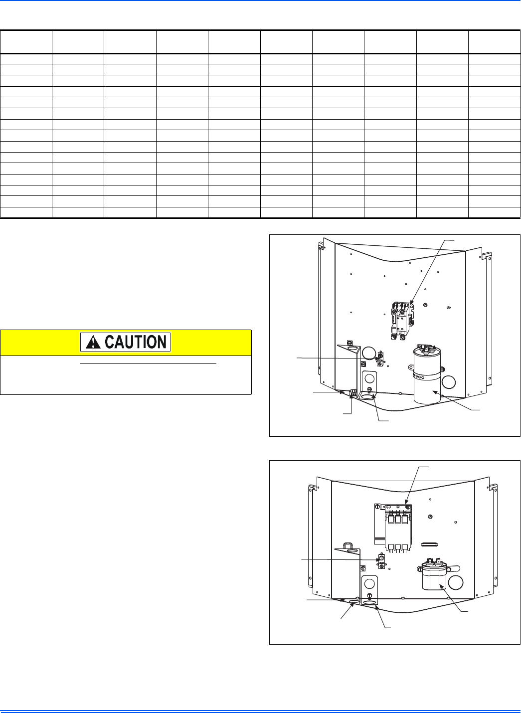
FIELD CONNECTIONS POWER WIRING
1. Install the proper size weatherproof disconnect switch outdoors
and within sight of the unit.
2. Remove the screws at the top and sides of the corner cover. Slide
corner cover down and remove from unit.
3. Run power wiring from the disconnect switch to the unit.
4. Route wires from disconnect through power wiring opening pro-
vided and into the unit control box as shown in Figures 6 & 7.
5. Install the proper size time-delay fuses or circuit breaker, and
make the power supply connections.
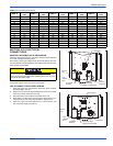
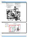
TABLE 2:
R-410A Saturation Properties
TEMP. °F
PRESSURE
PSIG
TEMP. °F
PRESSURE
PSIG
TEMP. °F
PRESSURE
PSIG
TEMP. °F
PRESSURE
PSIG
TEMP. °F
PRESSURE
PSIG
45 130 60 170 75 217 90 274 105 341
46 132 61 173 76 221 91 278 106 345
47 135 62 176 77 224 92 282 107 350
48 137 63 179 78 228 93 287 108 355
49 140 64 182 79 232 94 291 109 360
50 142 65 185 80 235 95 295 110 365
51 145 66 188 81 239 96 299 111 370
52 147 67 191 82 243 97 304 112 375
53 150 68 194 83 247 98 308 113 380
54 153 69 197 84 250 99 313 114 385
55 156 70 201 85 254 100 317 115 391
56 158 71 204 86 258 101 322 116 396
57 161 72 207 87 262 102 326. 117 401
58 164 73 211 88 266 103 331 118 407
59 167 74 214 89 270 104 336 119 412
All field wiring must USE COPPER CONDUCTORS ONLY and be
in accordance with Local, National, Fire, Safety & Electrical Codes.
This unit must be grounded with a separate ground wire in accor-
dance with the above codes.
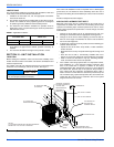
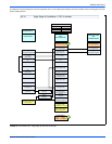
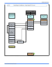
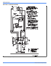
FIGURE 6: Outdoor Unit Control Box (Single Phase)
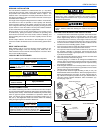
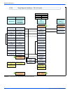
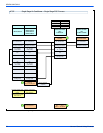
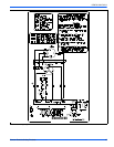
FIGURE 7: Outdoor Unit Control Box (Three Phase)
Dual
Run/Fan
Capacitor
Ground
Lug
“Fingered”
Bushing
Low
Voltage
Box
Reversible High
Voltage Conduit Plate
Contactor
Ground
Lug
“Fingered”
Bushing
Low
Voltage
Box
Reversible High
Voltage Conduit Plate
Fan
Capacitor
Contactor