


430645-YIM-D-0610
Johnson Controls Unitary Products 21
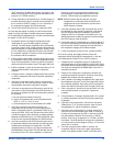
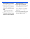
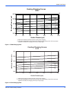
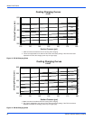
Defrost Operation
The defrost control board (DC) utilizes a time/temperature
defrost scheme. The DC repeats normal heating run cycles,
which must be completed, until one of the following conditions
is met and the DC enters defrost mode:
1. The DC satisfies its accumulated minimum run time. This
is factory set at 60 minutes, but is field adjustable to 30, 60
or 90 minutes.
2. The defrost switch(es) is closed. This normally open
switch is set to close at 28° F (+/-3°).
When the DC enters defrost mode, its on-board defrost relays
are powered. This energizes the reversing valve solenoid, de-
energizes the condenser fan motors and energizes the unit's
optional electric heater. The DC remains in defrost mode until
either of the following two conditions are met:
1. Both of the liquid line thermostats are open. Each is set to
open at 55 degrees (+/- 3).
2. The maximum defrost run time of 10 minutes is met.
The DC also contains a set of test pins. Placing a jumper
across these pins will result in the following actions:
• If the ASCD timer is active, it is now bypassed, allowing
the compressor to run.
• If the DC is in a lockout condition, the lockout is reset.
• If the compressor is running, the DC is forced into defrost
mode. The control will remain in defrost mode as long as
the jumper is in place. When the jumper is removed, the
control will terminate defrost mode.
NOTE: The DC has two flash codes that only initiate if the
jumper between the two pressure switch terminals is
removed or broken.
Blower Operation
After completing the specified time for fan on-delay, UCB closes
the coil of relay BR1.
• Relay BR1 sends a 24V signal to G1 of terminal block
TB2. It may be used to control operation of an indoor
blower.
The UCB disables the signal to BR1 after completing the fan
off-delay period.
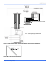
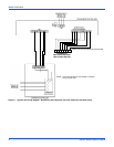
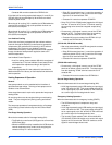
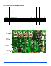
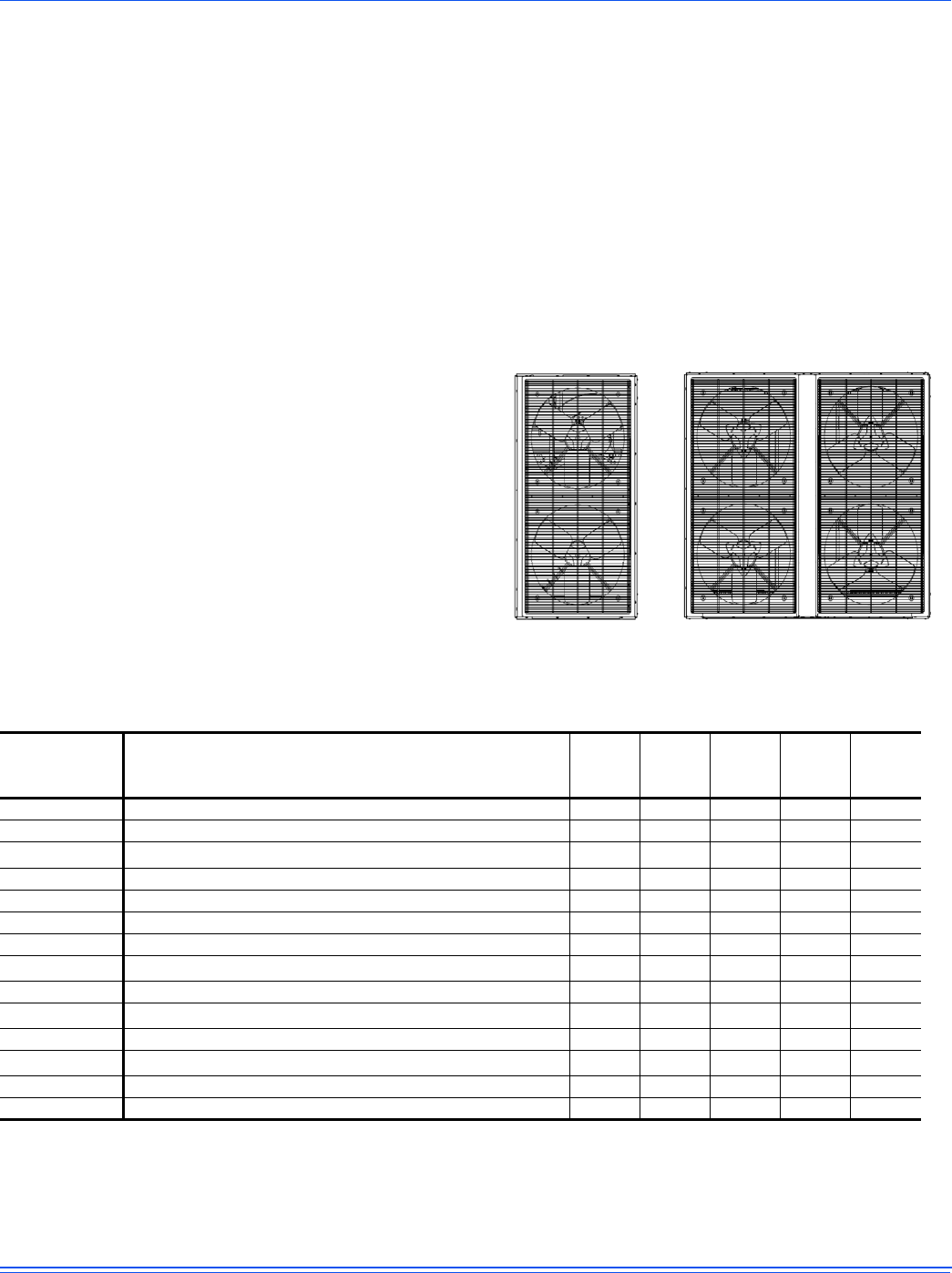
Figure 9: Fan Orientation, Control Box End
Rear
Front
Rear
Front
2
1
2
1
4
3
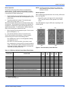
Table 10: PC090 thru 240 Unit Control Board Flash Codes
FLASH CODE DESCRIPTION
GREEN
LED
16
RED
LED
8
RED
LED
4
RED
LED
2
RED
LED
1
On Steady This is a Control Failure -----
1 Flash
Not Applicable -----
2 Flashes
Control waiting ASCD
1
1. Non-alarm condition.
Flashing Off Off On Off
3 Flashes
HPS1 Compressor Lockout Off Off Off On On
4 Flashes
Not Applicable -----
5 Flashes
LPS1 Compressor Lockout Off Off On Off On
6 Flashes
Not Applicable -----
7 Flashes
FS1 Compressor Lockout
2
2. Freeze - stat not applicable.
Off Off On On On
8 Flashes
Not Applicable -----
10 Flashes
Compressors Locked Out on Low Outdoor Air Temperature
1
Flashing On Off On Off
12 Flashes
Unit Locked Out due to Fan Overload Switch Failure Off On On Off Off
13 Flashes
Compressor Held Off due to Low Voltage
1
Flashing On On Off On
14 Flashes
EEPROM Storage Failure Off On On On Off
OFF
No Power or Control Failure OffOffOffOffOff