


364861-UIM-B-0708
Johnson Controls Unitary Products 31
ADJUSTMENT OF TEMPERATURE RISE
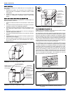
After about 5 minutes of operation, determine the furnace temperature
rise. Take readings of both the return air and the heated air in the ducts,
about six feet (1.83 m) from the furnace where they will not be affected
by radiant heat. Increase the blower speed to decrease the temperature
rise; decrease the blower speed to increase the rise.
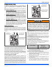
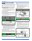
All direct-drive blowers have multi-speed motors. The blower motor
speed taps are located on the furnace control board in the blower com-
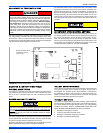
partment. Refer to Figure 40, "Furnace Control Board", and the unit-wir-
ing label to change the blower speed. To use the same speed tap for
heating and cooling, the heat terminal and cool terminal must be con-
nected using a jumper wire and connected to the desired motor lead.
Place all unused motor leads on Park terminals. Two park terminals are
provided.
ADJUSTMENT OF FAN CONTROL SETTINGS
This furnace is equipped with a time-on/time-off heating fan control. The
fan on delay is fixed at 30 seconds. The fan off delay has 4 settings (60,
90, 120 and 180 seconds). The fan off delay is factory set to 120 sec-
onds. The fan-off setting must be long enough to adequately cool the
furnace, but not so long that cold air is blown into the heated space. The
fan-off timing may be adjusted by positioning the jumper on two of the
four pins as shown in Figure 40, "Furnace Control Board".
SECTION X: SAFETY CONTROLS
CONTROL CIRCUIT FUSE
A 3-amp fuse is provided on the control circuit board to protect the 24-
volt transformer from overload caused by control circuit wiring errors.
This is an ATO 3, automotive type fuse and is located on the control
board.
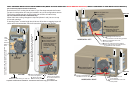
BLOWER DOOR SAFETY SWITCH
This unit is equipped with an electrical interlock switch mounted in the
burner compartment. This switch interrupts all power at the unit when
the panel covering the blower compartment is removed.
Electrical supply to this unit is dependent upon the panel that covers the
blower compartment being in place and properly positioned.
ROLLOUT SWITCH CONTROLS
These controls are mounted on the burner assembly. If the temperature
in the area surrounding burner exceeds its set point, the gas valve is
de-energized. The operation of this control indicates a malfunction in
the combustion air blower, heat exchanger or a blocked vent pipe con-
nection. Corrective action is required. These are manual reset controls
that must be reset before operation can continue.
PRESSURE SWITCHES
This furnace is supplied with two pressure switches, which monitor the
flow through the combustion air/vent piping and condensate drain sys-
tem. These switches de-energize the gas valve if any of the following
conditions are present. Refer to "CONDENSATE PIPING AND FUR-
NACE VENTING CONFIGURATION" for tubing connections.
1. Blockage of vent piping or terminal.
2. Failure of combustion air blower motor.
3. Blockage of combustion air piping or terminals.
4. Blockage of condensate drain piping.
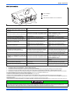
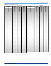
The temperature rise, or temperature difference between the return
air and the supply (heated) air from the furnace, must be within the
range shown on the furnace rating plate and within the application
limitations shown in Table 6, "Ratings & Physical / Electrical Data".
The supply air temperature cannot exceed the “Maximum Supply
Air Temperature” specified in these instructions and on the fur-
nace rating plate. Under NO circumstances can the furnace be
allowed to operate above the Maximum Supply Air Temperature.
Operating the furnace above the Maximum Supply Air Temperature
will cause premature heat exchanger failure, high levels of Carbon
Monoxide, a fire hazard, personal injury, property damage, and/or
death.
Do not energize more than one motor speed at a time or damage to
the motor will result.
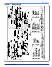
FIGURE 40: Furnace Control Board
PARK
PARK
HI COOL
HEAT
EAC-H
L1
XFMR
NEUTRALS
HUM
TWIN
60
90
120
180
BLOWER
OFF
DELAY
Y/Y2
W
R
G
C
Blower Off Delay Timer
Adjustment Jumper
(in seconds)
Main power to the unit must still be interrupted at the main power
disconnect switch before any service or repair work is to be done to
the unit. Do not rely upon the interlock switch as a main power dis-
connect.
Blower and burner must never be operated without the blower
panel in place.