


562156-UIM-A-0610
14 Johnson Controls Unitary Products
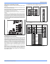
FAULT CODE DISPLAY
The control will display any fault code that is currently active using the
LED’s. The control will display the fault code, pause two seconds, and
display the fault again. The control will continue the fault code display
until the condition that caused the fault code no longer exists. If multiple
fault codes are present at the same time, the control will display only
the most recent fault.
Table 6 describes the operational faults that the control can detect. The
control displays these types of errors by flashing the LED1 (Red) and/or
LED2 (Green).
SENSOR OR SWITCH FAULT CODES
Table 7 describes the faults that the control can detect when a problem
is present with a sensor or switch. The control displays this type of error
by energizing LED1 (Red) constantly and flashing LED2 (Green).
These faults typically occur when an AC unit has been operating and a
problem occurs with a sensor or its wiring. These faults could also occur
during installation as the AC unit is configured.
WIRING RELATED FAULT CODES
Table 8 describes the faults that the control can detect when a problem
is present with the system wiring or jumper configurations. The control
displays this type of error by flashing LED1 (Red) and energizing LED2
(Green) constantly. These faults typically occur when the AC unit is first
installed or when a system component such as the room thermostat or
indoor unit is replaced or rewired.
LOCKOUT MODES
Soft Lockout
The control will cause a soft lockout during the following conditions.
Detailed descriptions of the conditions required for the control to enter
the soft lockout mode are contained in other sections of this document.
1. High-pressure switch
a. Two openings within six hours
2. Low-pressure switch
a. One opening of the switch for more than five seconds except
under certain conditions.
During the soft lockout mode, the control will do the following.
1. De-energize the compressor contactor outputs (M, M1, & M2).
2. Energize the LED’s with the appropriate flash codes as described
elsewhere in this document.
3. In communication applications the fault code will be stored in the
thermostat. (This feature is not available for non communicating
applications).
The control will reset the soft lockout condition when any of the follow-
ing occur following removal of the fault condition.
1. Power is cycled to the R or Y1 inputs of the control. This will cause
the soft lockout condition to be reset when the thermostat is satisfied
or when the thermostat is set to SYSTEM OFF and back to HEAT or
COOL mode.
2. The TEST terminals are shorted for more than two seconds.
When the soft lockout condition is reset, the control will stop displaying
the fault code and will respond to thermostat inputs normally.
Hard Lockout
If four soft lockouts occur within a twelve-hour period, the control will
cause a hard lockout condition. These soft lockouts can be caused by
the same or different conditions. The control will function in the same
way during soft and hard lockout conditions. The difference is in the
requirements for resetting the lockout condition. The control will reset
the hard lockout condition when any of the following occur following
removal of the fault condition.
1. Power is removed from the R input of the control.
2. The TEST terminals are shorted for more than two seconds.
A hard lockout condition will not be reset when the thermostat is satis-
fied or when the thermostat is set to SYSTEM OFF and back to HEAT
or COOL mode. Power (24 VAC) to the control must be removed and
reapplied.
When the hard lockout condition is reset, the control will de-energize
the LED’s and respond to inputs/communication normally.
Wiring or Setting Related Lockouts
The control will not operate the compressor when the following faults
occur. These faults can be reset using the same methods used to reset
a soft lockout. However, two occurrences of these faults will not cause a
hard lockout condition.
1. Presence of Y2 thermostat signal without Y1.
If a compressor wiring error is detected, the control will not operate the
compressor. Once the compressor wiring error has been detected,
power (24 VAC) must be cycled to the control for the control to sense
the wiring change and clear the lockout condition.
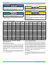
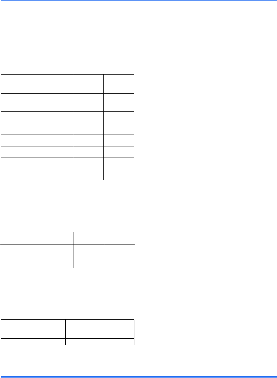
TABLE 6:
Operational Fault Codes
Description
LED1 Flash
Code (Red)
LED2 Flash
Code (Green)
Control Failure ON OFF
Operational Faults
High-pressure switch fault (not in
lockout yet)
1OFF
System in high-pressure switch
lockout
2OFF
System in low-pressure switch
lockout
4OFF
Low Voltage (<19.2VAC) preventing
further relay outputs
5OFF
Low Voltage (<16 VAC) stopped
current relay outputs
6OFF
High-pressure switch fault (with no
communication for compressor
operation and where Y1 and Y2
are not energized)
9ON
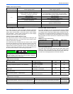
TABLE 7:
Sensor or Switch Fault Codes
Description
LED1 Flash
Code (Red)
LED2 Flash
Code (Green)
Outdoor ambient temperature
sensor failure (short)
ON 1
Outdoor ambient temperature
sensor failure (open)
ON 2
TABLE 8:
Wiring Related Fault Codes
Description
LED1 Flash
Code (Red)
LED2 Flash
Code (Green)
Compressor contactor miswire 1 ON
Y2 present without Y1 2 ON