


356486-UUM-H-0609
Johnson Controls Unitary Products 3
1. Examine the heat exchanger, vent pipe, combustion air passages,
vent connectors and chimney to be sure they are clear and free of
obstructions.
2. Examine the vent pipe making sure it is firmly in place, that it
slopes slightly upward and is physically sound without holes and
all of the connections are secure.
3. Examine the return-air duct connections to make sure they are
physically sound, sealed to the furnace casing, and the ducts ter-
minate outside the space containing the furnace.
4. Examine the furnace casing making sure the physical support is
sound without sagging, cracks or gaps. Examine the furnace base
making sure it is physically sound without cracks, gaps or sagging
and has a good seal.
5. Examine the furnace casing for obvious signs of deterioration.
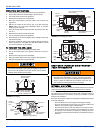
6. Examine the burner flames to make sure they are in good adjust-
ment. Refer to the pictorial sketch shown in Figure 7 as a compar-
ison to the actual flame.
7. Examine and replace external air filters as needed to make sure
they are not blocked, and proper airflow is provided to the furnace.
8. Examine any installed accessories or system components such as
evaporator coils to insure proper operation, drainage of conden-
sate, and that there is no water leakage or damage to the furnace
or any components.
SECTION III: START-UP AND SHUTDOWN
INSTRUCTIONS
Read the Instructions Below Before Trying to Start the
Furnace!
HOW YOUR GAS FURNACE WORKS
Your furnace is a very easy appliance to take for granted. Season after
season, it sits there in your home, keeping you warm and comfortable.
For this reason, you may never have given much thought to the way
your furnace operates. In order to get the safest and most efficient oper-
ation from your furnace, you should understand how your furnace does
its job.
When you set your thermostat to provide more heat in your home, you
are starting the heating cycle of the furnace. First, the inducer motor
starts to purge the heat exchanger of any remaining gases. Next, the
hot surface ignitor glows and after a warm-up period the gas valve
opens and ignition occurs. A short time later, the blower starts and dis-
tributes the warm air throughout the home. When the temperature set-
ting on your thermostat is reached, the gas valve closes, the main
burners are turned off, and the blower continues to run until the remain-
ing warm air in the system is distributed. When the blower stops, the
heating cycle has ended.
1. This appliance does not have a pilot. It is equipped with an ignition
device which automatically lights the burner. Do not try to light the
burner by hand.
2. BEFORE OPERATING; smell all around the appliance area for
gas. Be sure to smell next to the floor because some gas is
heavier than air and will settle on the floor.
3. Use only your hand to push the gas control switch to the ON posi-
tion. Never use tools. If the switch will not operate by hand, don’t
try to repair it, call a qualified service technician. Force or
attempted repair may result in a fire or explosion.
4. Do not use this appliance if any part has been under water. Imme-
diately call a qualified service technician to inspect the appliance
and to replace any part of the control system and any gas control,
which has been under water.
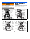
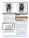
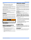
FIGURE 5: Component Location - 97% Modulating PSC Models FIGURE 6: Component Location - 97% Modulating ECM Models
Vent Pipe
Pressure
Switch
Manifold
Pipe
Rollout
Safety Switch
Gas Valve
Flame Sensor
Draft Inducer
Assembly
Ignitor
Safety
Door Switch
Control
Board
Electrical
Junction Box
Blower
Transformer
Capacitor
Condensate
Pan
Silicone Tube
PSC MOTOR
Limit Switch
(Behind gas valve)
Vent Pipe
Pressure
Switch
Manifold
Pipe
Rollout
Safety Switch
Gas Valve
Flame Sensor
Draft Inducer
Assembly
Limit Switch
(Behind gas valve)
Ignitor
Safety
Door Switch
Control
Board
Electrical
Junction Box
Blower
Transformer
Condensate
Pan
Silicone Tube
ECM MOTOR
Power Factor
Choke (Not
used on all
models)
FIGURE 7: Burner Flame Drawing (Upflow Configuration Shown)
Blue Cone Portion of Flame Should
Enter Heat Exchanger Tube
If you do not follow these instructions exactly, a fire or explo-
sion may result causing property damage, personal injury,
and/or loss of life.