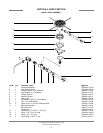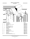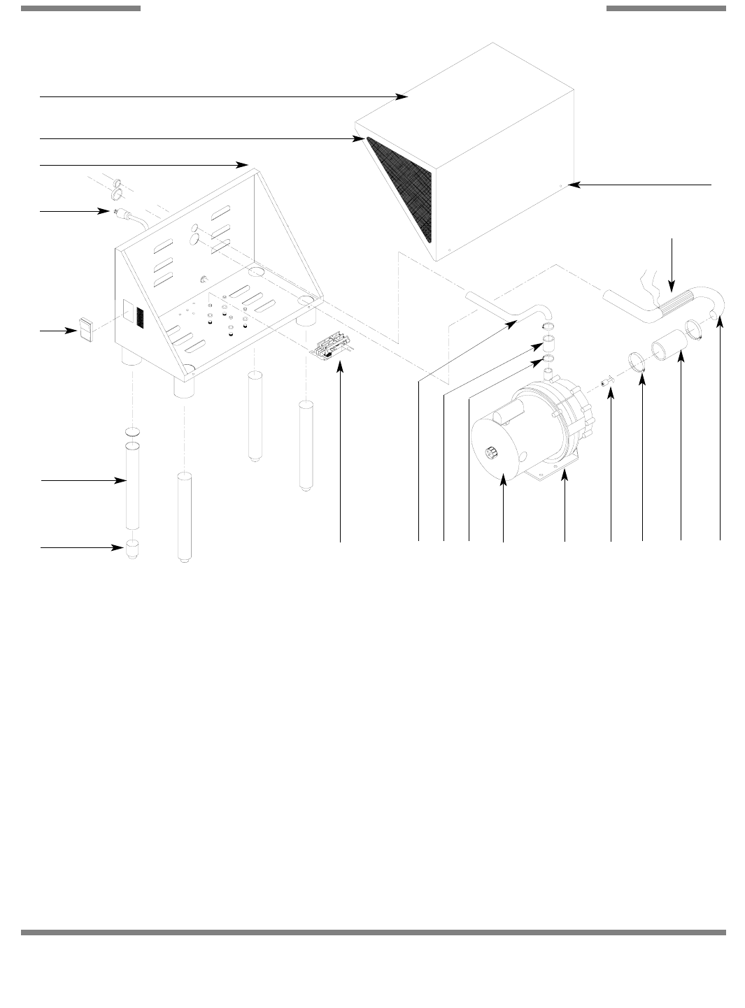
TEM QTY DESCRIPTION Mfg. No.
1 1 Cover Weldment 05700-003-38-43
2 1 Box Bottom Weldment 05700-003-38-49
3 2 Screw, 10-32 x 1/2" Long, Truss Head 05305-011-39-36
4 4 Leg Weldment 05700-021-67-92
5 4 Bullet Foot 05340-108-01-03
6 1 Pump and Motor Assembly, 1 HP 06105-021-69-18
6 1 Pump and Motor Assembly, 3/4 HP 06105-002-33-78
7 1 Chopper Assembly 05700-021-70-32
8 4 Locknut, 1/4"-20 with Nylon Insert 05310-374-01-00
9 4 Flat Washer, 1/4" 05311-174-01-00
10 1 Inlet Plumbing 05700-031-68-31
11 1 "J" Tube, Outlet 05700-021-68-60
12 1 Suction Connector Tube 05700-011-70-33
13 1 Discharge Connector Tube 05700-011-70-34
14 4 Hose Clamp, 2" 04730-719-01-37
15 1 Heater, Flexible, 120 Volts, 400 Watts 04540-021-70-21
16 1 Contactor, Motor 05945-109-05-69
17 1 Power Switch 05930-011-82-72
18 1 Power Cord 06145-011-70-28
19 1 Decal Whirl Wizard Logo, Left 09905-021-70-64
20 1 Decal, Whirl Wizard Logo, Right (Not Shown) 09905-021-70-59
Whirl Wizard Technical Manual 7610-011-70-65
Issued: 08-20-2007 Revised: N/A
SECTION 4: PARTS SECTION
MAIN ASSEMBLY
12
18
17
5
2
4
16
19
1
3
6
14
13
11
8, 9 7
14
15
12 10


