2
DANGER
WARNING
CAUTION
WARNING
Hazardous Fluids
can cause fire,
burns or death.
Safety Instructions
TO AVOID SERIOUS OR FATAL PERSONAL
INJURY OR MAJOR PROPERTY DAMAGE, READ AND
FOLLOW ALL SAFETY INSTRUCTIONS IN MANUAL AND
ON PUMP.
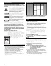
This is a SAFETY ALERT SYMBOL. When
you see this symbol on the pump or in the
manual, look for one of the following signal
words and be alert to the potential for
personal injury or property damage.
Warns of hazards that WILL cause serious
personal injury, death or major property
damage.
Warns of hazards that CAN cause serious
personal injury, death or major property
damage.
Warns of hazards that CAN cause personal
injury or property damage.
NOTICE: Indicates special instructions which are very
important and must be followed.
THIS MANUAL IS INTENDED TO ASSIST IN THE
INSTALLATION AND OPERATION OF THIS UNIT
AND MUST BE KEPT WITH THE PUMP.
THOROUGHLY REVIEW ALL INSTRUCTIONS AND
WARNINGS PRIOR TO PERFORMING ANY WORK
ON THIS PUMP.
MAINTAIN ALL SAFETY DECALS.
NOTICE:INSPECT UNIT FOR DAMAGE AND
REPORT ALL DAMAGE TO THE CARRIER
OR DEALER IMMEDIATELY. DO NOT USE
PUMP IF DAMAGE IS SUSPECTED.
UNITS NOT DESIGNED FOR USE
WITH HAZARDOUS LIQUIDS OR
FLAMMABLE GASES.
Description and Specifications
• The Model GT embraces a line of end suction, single
stage, self-priming centrifugal pumps for lawn sprinkling,
HVAC systems, and general water transfer.
• Casing is cast iron construction with tapped openings
provided for vacuum gauge and casing drain.
• Impellers are enclosed design, glass filled Noryl
TM
,
threaded directly on motor shaft.
• Standard motors are NEMA standard, 3500 RPM, open
drip proof enclosure.
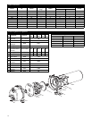
Engineering Data
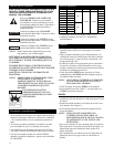
Model HP Ph/Hz Suction Discharge Wt. lbs.
GT07
3
⁄4 48
GT10 1 52
GT15 1
1
⁄2 1/60 60
GT20 2 65
GT30 3 76
GT073
3
⁄4 49
GT103 1 52
GT153 1
1
⁄2 3/60 55
GT203 2 69
GT303 3 71
• Maximum Liquid Temperature: 160ºF (71ºC)
• Maximum Starts per Hour: 20 – evenly distributed
Piping
• Pump MUST be installed horizontally on a solid flat
surface, with discharge on top.
• Allow adequate space for servicing and ventilation.
Protect the unit from weather and water damage due to
rain or flooding or freezing temperatures.
• Piping should be no smaller than the suction and
discharge connections and kept short as possible,
avoiding unnecessary fittings to minimize friction losses.
• All piping MUST be independently supported and
MUST NOT place any piping loads on the pump.
NOTICE: DO NOT FORCE PIPING INTO PLACE
AT PUMP SUCTION AND DISCHARGE
CONNECTIONS.
• All pipe joints MUST be airtight.
• The use of Teflon
TM
tape, or equivalent, is recommended
for ALL pipe joints.
SUCTION
• Total suction lift, including elevation and pipe friction
loss, should not exceed 25 feet of head.
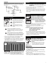
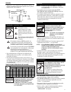
• Install an airtight union in the suction line close to the
pump. See Figure 1.
• Installation of a foot valve at liquid source is
recommended.
NOTICE: FOR INSTALLATIONS WITH LONG
SUCTION PIPING, BOTH A FOOT VALVE
AND A CHECK VALVE ARE
RECOMMENDED.
• To avoid air pockets, no part of the piping should be
above the pump suction connection and piping should
slope upward from liquid source.
• For installations with long suction piping, fill the suction
pipe with water before connecting to pump.
1
1
⁄2” NPT 1
1
⁄2” NPT


