


Head and Torso Supports 2 Part No. 1026310
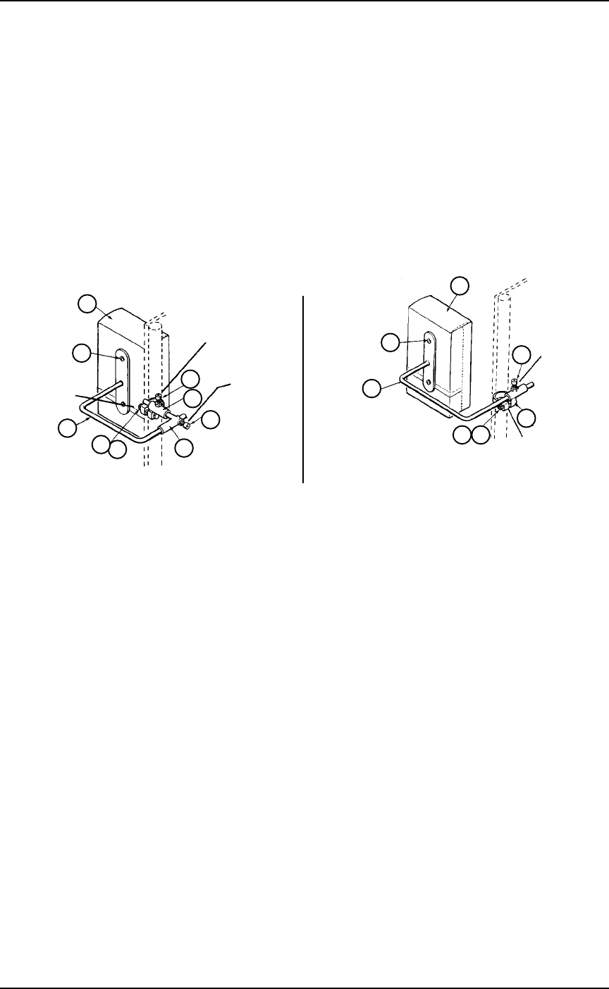
TORSO SUPPORTS MODEL NOS. 1164 AND 3040 (FIGURE 2)
1. Mount the torso support to the back upright of the chair; which includes the
following items:
Headrest/Torso Pad Assembly (Item 1)
Panhead Screw (Item 2)
Torso Bracket Cover (Item 3)
(Model No. 1164 - Only)
Support Rod (Item 4)
Socket Screw (Item 6)
Torso Support Bracket (Item 5)
Pad Support Sub-Assembly (Item 8)
Bracket Clamp (Item 7)
Lug Screw (Item 10)
Locknut (Item 11)
2. LEFT or RIGHT adjustments can be accomplished by loosening the socket screw
(Item 6) on the bracket clamp (Item 7 - Model No. 3040 and the support rod
(Item 4 - Model No. 1164) with an Allen wrench.
NOTE: The support rod (Item 4) MUST BE assembled to the torso support bracket
(Item 5) before installation of Model No. 1164.
Bracket Clamp (Item 7)
Adjustment Bracket Assembly (Item 9)
Lug Screw (Item 10)
Locknut (Item 11)
2. LEFT or RIGHT adjustments can be accomplished by loosening the socket screw
(Item 6) on the adjustable bracket assembly (Item 9 - Model No. 3045) (Item 7 -
Model 3046) with an Allen wrench.
3. UP or DOWN adjustment are made by loosening the lug screw and the
locknut (Items 10 and 11).
4. FRONT and BACK adjustments are made by loosening the socket screw (Item 6)
on the bracket clamp (Item 7 - Model No. 3045 Only).
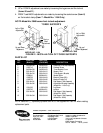
FIGURE 1 - INSTALLATION OF HEAD SUPPORTS
HEAD SUPPORTS
MODEL NO. 3045 NON-RECLINER
1
2
Front or Back
Adjustment
Left
or Right
Adjustment
12
11
10
Up and Down
Adjustment
9
6
6
7
13
MODEL NO. 3046 RECLINERS W PILLOW
1
2
13
10
11
6
7
Left
or Right
Adjustment
Up and Down
Adjustment