


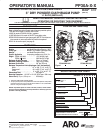
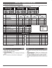
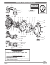
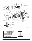

PARTS LIST / PP30A-X-X AIR SECTION
n
n
n
n
n
n
n
n
n
n
Kn
n
n
n
n
n
n
n
LĂn
K Fluid Section Kit parts, see page 6.
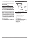
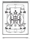
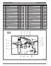
AIR MOTOR SECTION SERVICE
S Air Motor Section Service is continued from Fluid Section repair.
S Inspect and replace old parts with new parts as necessary. Look for
deep scratches on metallic surfaces, and nicks or cuts in O" rings.
S Take precautions to prevent cutting O" rings upon installation.
S Lubricate O" rings with Lubriplate FMLĆ2 grease.
S Do not overĆtighten fasteners, refer to torque specification block on
view.
S ReĆtorque fasteners following restart.
S SERVICE TOOLS - To aid in the installation of (168) O" rings onto
the (167) pilot piston, use tool # 204130ĆT, available from ARO.
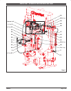
PILOT VALVE DISASSEMBLY
1. A light tap on (118) should expose the opposite (121) sleeve, (167)
pilot piston and other parts.
2. Remove (170) sleeve, inspect inner bore of sleeve for damage.
PILOT VALVE REASSEMBLY
1. Clean and lubricate parts not being replaced from service kit.
2. Install new (171 and 172) O" rings, replace (170) sleeve.
3. Install new (168) O" rings and (169) seal Ć Note the lip direction. LuĆ
bricate and replace (167).
4. Reassemble remaining parts, replace (173 and 174) O" rings.
MAJOR VALVE DISASSEMBLY
1. Remove (135) valve block and (233) adapter plate, exposing (166
and 132) gaskets and (176) checks.
2. Remove (233) adapter plate, releasing (140) valve insert, (141)
valve plate, (199, 200 and 241) gaskets and (231, 243 and 244) O"
rings.
3. Remove (136) plug and (137) O" ring, releasing (111) spool.
MAJOR VALVE REASSEMBLY
1. Install new (138 and 139) U" cups on (111) spool -
.
2. Insert (111) spool into (135) valve housing.
3. Install (137 and 242) O" rings on (136) plug and assemble plug to
(135) valve housing, securing with (105) screws.
4. Install (140) valve insert, (141) valve plate, (199) gasket and (231,
243 and 244) O" rings into (135) valve housing. NOTE: Assemble
(140) valve insert with dished" side toward (141) valve plate. AsĆ
semble (141) valve plate with part number identification toward
(140) valve insert.
5. Assemble (200 and 241) gaskets and (233) adapter plate to (135)
valve housing, securing with (240) screws.
6. Assemble (132 and 166) gaskets and (176) checks to (101) center
body.
7. Assemble (135) valve housing and components to (101) center
body, securing with (134) screws.