


PM05P-X-X-A02PAGE 6 OF 8
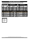
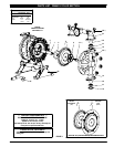
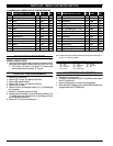
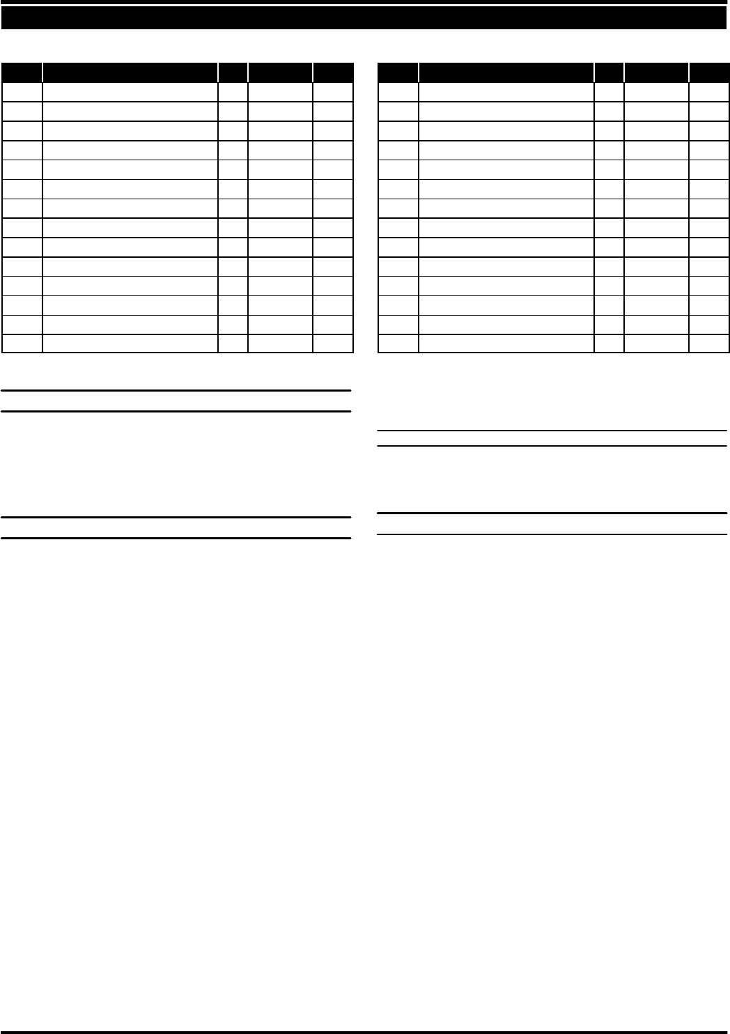
PARTS LIST / PM05P-X AIR MOTOR SECTION
(n) Indicates parts included in 637141 Air Section Repair Kit.
ITEM DESCRIPTION (Size in inches) Qty Part No. [Mtl] ITEM DESCRIPTION (Size in inches) Qty Part No. [Mtl]
101 Motor Body (1) 93091 [P]
n102
“O” Ring (3/32” x 1” o.d.) (2) Y325-117 [B]
V103
Sleeve (1) 93087 [Bz]
V104
Snap Ring, (13/16”) (2) 37285 [C]
111 Spool (1) 93085 [D]
118 Piston (1) 93088 [C]
n119
“O” Ring (1/8” x 3/4” o.d.) (4) 93075 [U]
V120
Spacer (3) 115959 [Z]
n122
Snap Ring (1/2”) (2) 77802 [C]
129 Muffler (1) 66972 [P]
129 Exhaust Cover (option) (1) 93092 [PS]
n130
Gasket (1) 93107 [SY]
131 Bolt (5/16” - 18 x 1-1/4”) (16) 93095 [SS]
n132
Gasket (1) 93339-1 [B]
133 Washer (9/32” i.d.) (4) 93096 [SS]
134 Cap Screw (1/4”-20x5”) (4) Y6-419-T [SS]
135 Valve Block (1) 93090 [P]
136 Plug (1) 93086 [D]
n137
“O” Ring (3/32” x 1-1/2” o.d.) (1) Y325-125 [B]
n138
“U” Cup Packing (1/8” x 1” o.d.) (1) 94395 [U]
n139
“U” Cup Packing (1/8” x 1- 7/16” o.d.) (1) 96383 [B]
n140
Valve Insert (1) 93276 [CK]
n141
Valve Plate (1) 93275 [CK]
142 Washer (2) 116038 [Z]
143 Plate (2) 93089 [SS]
201 Muffler (option) (1) 93110 [C]
n
Keylube, “O” Ring Lubricant (1) 93706-1
Keylube, 10 Pack 637175
V “Smart Parts” keep these items on hand in addition to the Service Kits for fast repair and reduction of down time.
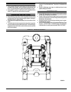
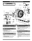
DIAPHRAGM PUMP SERVICE
GENERAL SERVICE NOTES:
S Inspect and replace old parts with new parts as necessary.Look for
deep scratches on metallic surfaces, and nicks or cuts in “O” rings.
S 7/16” wrench, 1/2” wrench, 7/16” socket, 1/2” socket, torque
wrench (measuring inch pounds), “O” ring pick.
FLUID SECTION DISASSEMBLY
1. Remove (61) top manifold.
2. Remove (19) “O” rings, (21) seats and (22) balls.
3. Remove (60) bottom manifold.
4. Remove (19) “O” rings, (21) seats and (22) balls.
5. Remove (15) fluid caps.
6. Remove (14) bolt, (6) diaphragm washer, (7) or (7 / 8) diaphragms
and (5) washer.
7. Remove (1) connecting rod from air motor.
8. Carefully remove remaining (14) bolt, (6) diaphragm washer, (7) or
(7 / 8) diaphragms and (5) washer from (1) connecting rod. Do not
mar surface of connecting rod.
9. Remove (2) “O” ring from connecting rod.
Note1:AMajorValveServiceAssemblyisavailableseparatelywhichincludesitems:111,
132, 135 - 141. Order part no 66362.
MATERIAL CODE
[B] = Nitrile [D] = Acetal [SY] = Syn-Seal
[Bz] = Bronze [P] = Polypropylene [U] = Polyurethane
[C] = Carbon Steel [PS] = Polyester [Z] = Zinc
[CK] = Ceramic [SS] = Stainless Steel
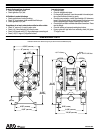
FLUID SECTION REASSEMBLY
S Reassemble in reverse order.
S Lubricate(1)connectingrod and(2)“O” ringwithKey-Lubeor equiv-
alent “O” ring lubricant.
S Install (5) washers with i.d. chamfer toward diaphragm.
S WhenreplacingPTFEdiaphragms, installthe 93465Santoprene di-
aphragm behind the PTFE diaphragm.