Page 3 of8PF20R-X-B
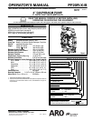
GENERAL DESCRIPTION
The ARO diaphragm pump offers high volume delivery even at low air
pressure and a broad range of material compatibility optionsavailable.
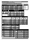
Refer to the modeland option chart. ARO pumps feature stallresistant
design, modular air motor / fluid sections.
Air operated double diaphragm pumps utilize a pressure differential in
theairchamberstoalternatelycreatesuctionandpositivefluidpressure
in the fluid chambers, flap checks insure a positive flow of fluid.
Pump cycling will begin as air pressure is applied and it willcontinue to
pump andkeep up withthe demand. Itwill build andmaintain line pres-
sure and will stopcycling once maximum line pressureis reached (dis-
pensing device closed) and will resume pumping as needed.
AIR AND LUBE REQUIREMENTS
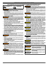
WARNING
EXCESSIVE AIR PRESSURE. Can cause pump
damage, personal injury or property damage.
S Afiltercapableoffilteringoutparticleslargerthan50micronsshould
beusedontheairsupply.Thereisnolubricationrequiredotherthan
the “O” ring lubricant which is applied during assembly or repair.
S If lubricated air is present, make sure that it is compatible with the
Nitrile “O” rings in the air motor section of the pump.
OPERATING INSTRUCTIONS
S Always flush the pump with a solvent compatible with the material
beingpumpedifthematerialbeingpumpedis subjectto“settingup”
when not in use for a period of time.
S Disconnecttheairsupplyfromthepumpifitistobeinactiveforafew
hours.
S Theoutletmaterialvolumeisgovernednotonlybytheairsupplybut
alsobythematerialsupplyavailableattheinlet.Thematerialsupply
tubingshouldnot betoosmallorrestrictive. Besurenotto usehose
which might collapse.
S When the diaphragm pump is used in a forced-feed (flooded inlet)
situation,it isrecommended thata“CheckValve” beinstalledat the
air inlet.
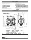
S Secure the diaphragm pump legs to a suitable surface to insure
against damage by vibration.
PARTS AND SERVICE KITS
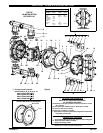
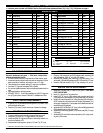
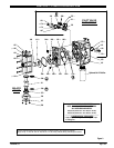
Refertothepartviewsanddescriptionsasprovidedonpage4through7
for parts identification and Service Kit information.
S Certain ARO “SmartParts” areindicated whichshould be available
for fast repair and reduction of down time.
S Service kits are divided to service two separate diaphragm pump
functions:1.AIRSECTION,2.FLUIDSECTION.TheFLUIDSEC-
TION isdivided further tomatch typicalpart MATERIAL OPTIONS.
MAINTENANCE
S Provide a clean work surface to protect sensitive internal moving
partsfromcontaminationfromdirtand foreignmatterduringservice
disassembly and reassembly.
S Keep good records of service activity and include pump in preven-
tive maintenance program.
S Before disassembling, empty captured material in the outlet man-
ifold by turning the pump upside down to drain material from the
pump.
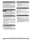
FLUID SECTION DISASSEMBLY
1. Remove (61) top manifold, (60) bottom manifold and (53) manifold
elbow.
2. Remove the flap valve cartridge / seat assemblies.
3. Remove (15) fluid caps.
NOTE:Only PTFEdiaphragmmodels useaprimarydiaphragm (7)and
a backup diaphragm(8). Refer tothe auxiliary view inthe Fluid Section
illustration.
4. Remove the (6) diaphragm washer, (7) diaphragm and (5) backup
washer.
NOTE: Do not scratch or mar the surface of (1) diaphragm rod.
FLUID SECTION REASSEMBLY
S Reassemble in reverse order. Refer to the torque requirements on
page 5.
S Clean and inspect all parts. Replace worn or damaged parts with
new parts as required.
S Lubricate (1) diaphragm rod and (144) “U” cup with LubriplateR
FML-2 grease (94276 grease packet is included in service kit).
S FormodelswithPTFEdiaphragms:Item(8)Santoprenediaphragm
isinstalled withthe sidemarked “AIRSIDE”towards thepump cen-
ter body. Install the PTFE diaphragm (7) with the side marked
“FLUID SIDE” towards the (15) fluid cap.
S Re-check torquesettings after pumphas beenre-started and runa
while.
VitonRistrademarkoftheDuPontCompany, S KynarRisaregisteredtrademarkofPenwaltCorp.
SantopreneRisaregisteredtrademarkofMonsantoCompany,licensedtoAdvancedElastomerSystems,L.P. S LubriplateRisaregisteredtrademarkofLubriplateDivision(FiskeBrothers)
(en)


