


Page 9 of 12 PX01X-XXX-XXX-AXXX (en)
PE01X OPTION WIRING DIAGRAMS
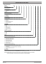
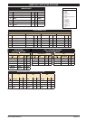
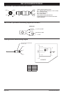
End of Stroke / Cycle Sensor Pinout, M12 Connector
1
2
4
3
CABLE ASSEMBLY WIRING COLORS:
PIN 1 - BROWN, POSITIVE VOLTAGE (+10 TO +30 VDC)
PIN 2 - WHITE, NOT USED
PIN 3 - BLUE, ZERO VOLTS
PIN 4 - BLACK, SIGNAL
NOTE: WIRING COLORS ARE BASED ON
AUTOMATION DIRECT CD12L AND CD12M 4-POLE
CABLE ASSEMBLIES.
PIN
2
PIN 3
PIN 4
PIN 1
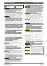
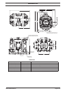
End of Stroke / Cycle Sensor Pinout Wiring Diagram (No Connector)
1 BROWN
PNP Output
L
L -
+10 TO +30 VDC
0 VDC
Load 200 mA MA
X
4 BLACK
3 BLUE
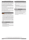
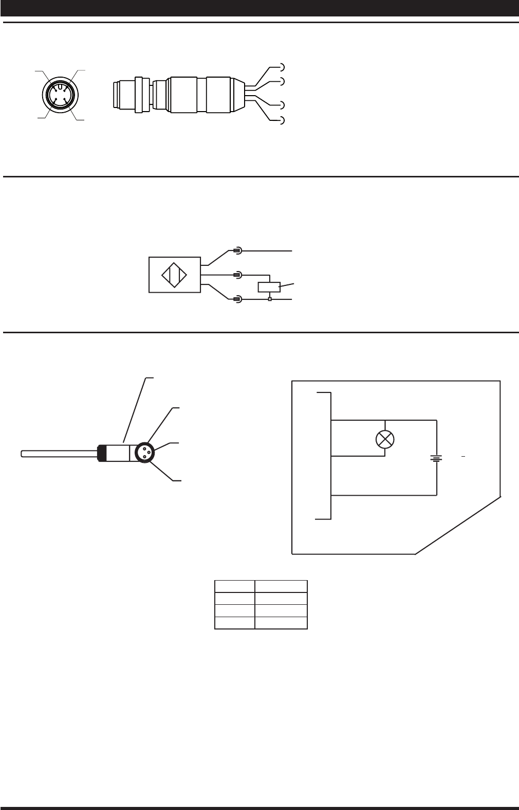
Diaphragm Failure Detector Wiring Diagram
TURCK (PICOFAST) CONNECTOR
PSW 3M -*/S90
A
C
B
BN
PIN A
SCHEMATIC
SENSOR
SCHEMATIC
BLK
PIN C
LOAD
40 mA
MAX
-
+
BU
PIN B
24.0 + 10%
V.D.C
PINOUT FUNCTION
A + 24 VDC
B 0 VDC
C SIGNAL