


PD10X-X-XPage 6 of 8
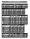
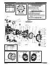
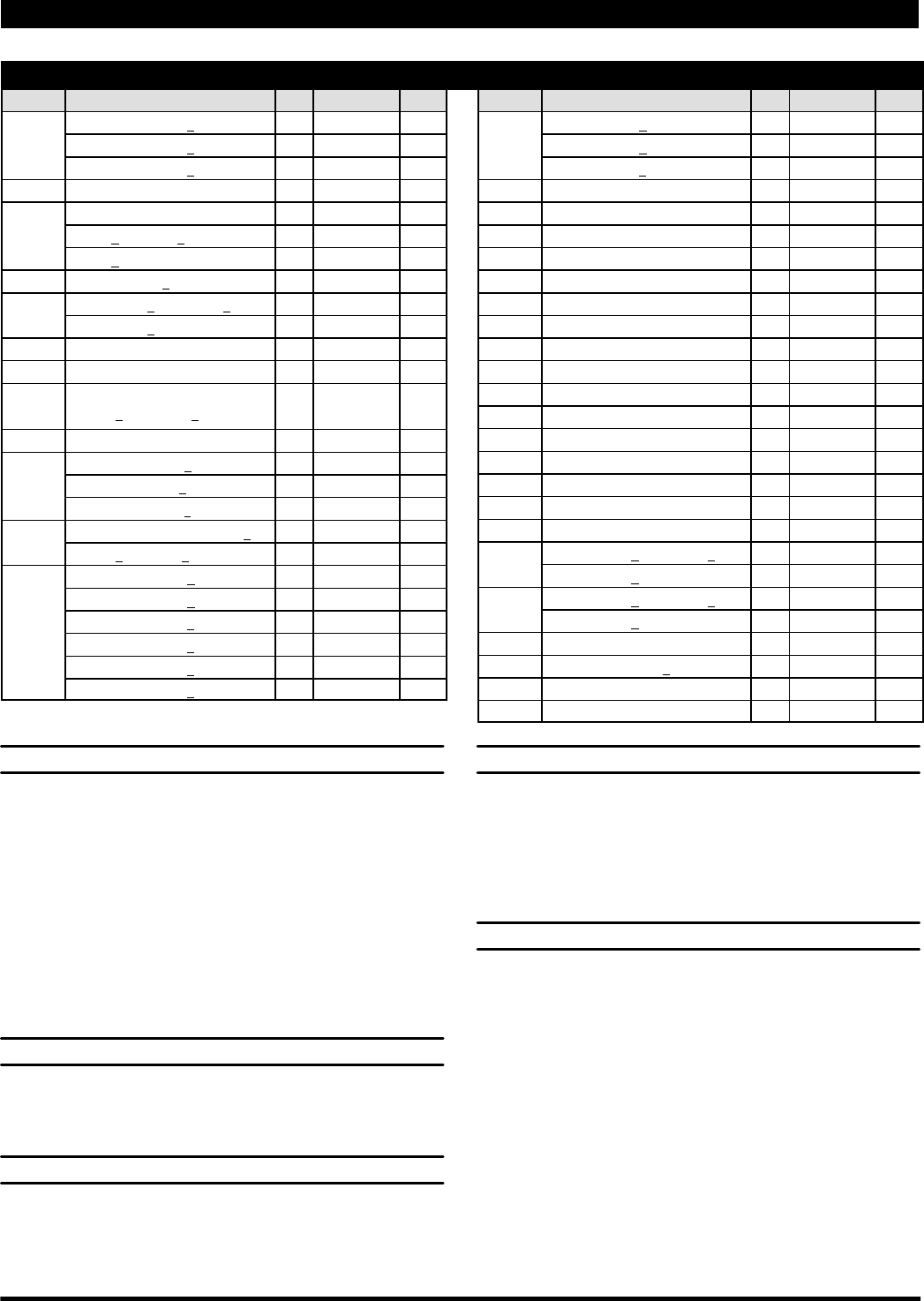
PARTS LIST / PX10X-X-X AIR SECTION
n Indicates parts included in 637397 Air Section Service Kit shown below and items (70), (144), (175) and (180) shown on page 4.
AIR MOTOR PARTS
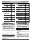
Item Description (size) Qty Part No. [Mtl] Item Description (size) Qty Part No. [Mtl]
101 Center Body (PX10A-X-X) (1) 95888 [A]
(PX10R-X-X) (1) 95970 [P]
(PX10S-X-X) (1) 95901 [SS]
103 Bushing (1) 96000 [D]
105 Screw (M6x1-6g)
(PX10A-X and PX10S-X) (16 mm long) (4) 95991 [SS]
(PX10R-X) (130 mm long) (4) 95886 [SS]
107 End Plate (PX10R-X-X only) (2) 95840 [SS]
111 Spool (PX10A-X-X and PX10S-X-X) (1) 95835 [D]
(PX10R-X-X) (1) 96293 [D]
118 Actuator Pin (2) 95999 [SS]
121 Sleeve (2) 95123 [D]
128 Pipe Plug (1/8 - 27 N.P.T. x 0.27”)
(PX10A
-X-X and PX10S-X-X only)
(1) Y17-50-S [SS]
n 132 Gasket (1) 96170 [B]
133 Washer (1/4”) (PX10A-X-X) (3) Y117-416-C [C]
(M6) (PX10R-X-X) (6) 95931 [SS]
(1/4”) (PX10S-X-X) (3) Y14-416-T [SS]
134 Screw (M6 x 1 - 6g x 20 mm) (PX10R-X) (6) 95887 [SS]
(PX10A-X and PX10S-X-X) (4) 95887 [SS]
135 Valve Block (PD10A-X-X) (1) 95942-3 [Z]
(PD10R-X-X) (1) 96174-1 [P]
(PD10S-X-X) (1) 95939-3 [SS]
(PE10A-X-X) (1) 95942-4 [Z]
(PE10R-X-X) (1) 96174-2 [P]
(PE10S-X-X) (1) 95939-4 [SS]
136 End Cap (PX10A-X-X) (1) 95941 [Z]
(PX10R-X-X) (1) 95833 [P]
(PX10S-X-X) (1) 95938 [SS]
n 137 Gasket (1) 95844 [B]
n 138 “U” Cup (3/16” x 1-5/8” o.d.) (1) Y186-53 [B]
n 139 “U” Cup (3/16” x 1-1/8” o.d.) (1) Y186-49 [B]
140 Valve Insert (1) 95838 [AO]
141 Valve Plate (1) 95885 [AO]
n 166 Gasket (1) 96171 [B]
n 167 Pilot Piston (includes 168 and 169) (1) 67164 [D]
168 “O” Ring (3/32” x 5/8” o.d.) (2) 94433 [U]
169 “U” Cup (1/8” x 7/8” o.d.) (1) Y240-9 [B]
170 Piston Sleeve (1) 94081 [Br]
n 171 “O” Ring (3/32” x 1-1/8” o.d.) (1) Y325-119 [B]
n 172 “O” Ring (1/16” x 1-1/8” o.d.) (1) Y325-22 [B]
n 173 “O” Ring (3/32” x 1-3/8” o.d.) (2) Y325-123 [B]
K n 174 “O” Ring (1/8” x 1/2” o.d.) (2) Y325-202 [B]
n 176 Diaphragm (check valve) (2) 95845 [SP]
181 Roll Pin (5/32” o.d. x 1/2” long) (4) Y178-52-S [SS]
n 200 Gasket (PX10A-X-X and PX10S-X-X) (1) 96172 [B]
(PX10R-X-X) (1) 95842 [B]
201 Muffler (PX10A-X-X and PX10S-X-X) (1) 350-568
(PX10R-X-X) (1) 93139 [P]
233 Adapter Plate (1) 95832 [P]
236 Nut (M6 x 1 - 6g) (PX10R-X-X only) (4) 95924 [SS]
L n Lubriplate FML-2 Grease (1) 94276
Lubriplate Grease Packets (10) 637308
K Fluid Section Service Kit Parts, see page 4.
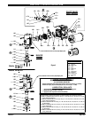
AIR MOTOR SECTION SERVICE
Service is divided into two parts - 1. Pilot Valve, 2. Major Valve.
GENERAL REASSEMBLY NOTES:
S Air Motor Section Service is continued from Fluid Section repair.
S Inspect and replace old parts with new parts as necessary. Look for
deep scratches on surfaces, and nicks or cuts in “O” rings.
S Take precautions to prevent cutting “O” rings upon installation.
S Lubricate “O” rings with Lubriplate FML-2 grease.
S Do not over-tighten fasteners, refer to torque specification block on
view.
S Re-torque fasteners following restart.
S SERVICE TOOLS -- To aid in the installation of (168) “O” rings onto
the (167) pilot piston, use tool # 204130-T, available from ARO.
PILOT VALVE DISASSEMBLY
1. A light tap on (118) should expose the opposite (121) sleeve, (167)
pilot piston and other parts.
2. Remove (170) sleeve, inspect inner bore of sleeve for damage.
PILOT VALVE REASSEMBLY
1. Clean and lubricate parts not being replaced from service kit.
2. Install new (171 and 172) “O” rings, replace (170) sleeve.
3. Install new (168)“O”rings and (169) seal - Note the lip direction. Lu-
bricate and replace (167).
4. Reassemble remaining parts, replace (173 and 174) “O” rings.
MAJOR VALVE DISASSEMBLY
1. Remove (135) valve block and (233) adapter plate, exposing (132
and 166) gaskets and (176) checks.
2. Inserta small flatblade screwdriver intothe notchinthe sideof (135)
valve blockand pushin ontab toremove (233)adapter plate,releas-
ing (140) valve insert, (141) valve plate, (200) gasket.
3. Remove (136) end cap and (137) gasket, releasing (111) spool.
MAJOR VALVE REASSEMBLY
1. Install new (138 and 139) “U” cups on (111) spool -- LIPS MUST
FACE EACH OTHER.
2. Insert (111) spool into (135) valve block.
3. Install(137) gasket on(136) end capandassemble endcap to (135)
valve block, securing with (107) end plates (where applicable) and
(105) screws.
4. Install(140)valve insert and(141) valve plate into(135)valve block.
NOTE: Assemble (140) valve insert with “dished” side toward (141)
valve plate. Assemble (141) valve plate with part number identifica-
tion toward (140) valve insert.
5. Assemble(200) gasket and(233) adapter plateto(135) valve block.
NOTE: Assemble (233) adapter plate with notched side down.
6. Assemble (132 and 166) gaskets and (176) checks to (101) body.
7. Assemble (135) valve block and components to (101) body, secur-
ing with (134) screws.