


Page2of4
NP318X01-X
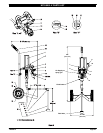
NP318X01-X PARTS LIST
Item Description (size) Qty Part No. Item Description (size) Qty Part No.
Models NP318C01-X (cart mount) include items 1 thru 33.
Models NP318W01-X (wall mount) include items 1 thru 25.
1 Two-Ball Pump (models NP318X01-1) (1) NM2318B-13-C43
(models NP318X01-2) (1) NM2318B-13-L43
2 Pump Bracket (1) 95015
3 90_ Street Elbow (1/4 - 18 N.P.T.) (3) Y43-2-C
4 Adapter (1/8- 27 N.P.T.malex 1/4 -18 N.P.T.
female)
(2) Y167-1
5 “O” Ring (3/32” x 1-5/16” o.d.) (1) Y325-122
6 Shut-Off Valve (1/4 - 18 N.P.T.F.) (1) 104390- 2
7 Gauge (0 - 60 p.s.i.) (1) 100090
8 Regulator (0 - 50 p.s.i.) (1) B27122-100
9 Elbow (1/4 - 18 N.P.T. male x 1/2” o.d. tube) (2) 59756-162
10 Tubing (1/2” o.d. x 10” long) (1) 94978-X =
11 Gauge (0 - 160 p.s.i. / 0 - 11 bar) (1) 100091
12 Regulator (0 - 125 p.s.i.) (1) B27122-000
13 90_ Street Elbow (1/2 - 14 N.P.T.) (1) Y43-4-S
14 Adapter (1/2 - 14 N.P.T.F. male x 1/2 - 14
N.P.S.M. male)
(1) 95608
15 Hose Assembly (1/2 - 14 N.P.S.M. female
x 1/2 - 14 N.P.T.F. male x 60”)
(1) 623510-5
16 90_ Elbow (1/2 - 14 N.P.T.) (1) Y43-14-S
17 Bushing (1/2 - 14 N.P.T.F. - 1 x 13-5/8”) (1) 95108-1
18 Screen (1/2 - 14 N.P.S.) (1) 74047-1
19 Suction Hose Assembly (1) 67359-1
20 Adapter (1/4 - 18 N .P.T.F - 1 x 1/4 - 18-1/2
N.P.S.M.)
(2) 96120
21 Tee (1/4 - 18 N.P.T.F.) (1) 94039
22 Swivel Union(1/4 -18 N.P.T.F. -1 male x1/4
- 18 N.P.S.M. female)
(1) 75364
23 Pressure Relief Valve (80 p.s.i. / 5.5 bar) (1) 95604
24 Washer (1/4”) (3) Y13-4-C
25 Hex Cap Screw (1/4” - 20 x 1/2”) (3) Y6-41-C
The following items are included in models NP318C01-X only.
26 Hex Cap Screw (3/8” - 16 x 3/4”) (4) Y6-63-C
27 Nut (3/8” - 16) (4) Y12-6-C
28 Lock Washer (3/8”) (4) Y14-616-C
29 Handle Grip (1) 71747-1
30 Cart Assembly (1) 67268
31 Wheel (8” o.d. x 1-1/2”) (2) 71045-1
32 Spacer (1/2” i.d. x 7/8” o.d.) (4) 77750
33 Cotter Pin (1/8” o.d. x 1”) (2) Y15-43
Cart Assembly(includesitems29 thru33) (1) 67270
= Bulk Tubing (1/2” o.d. x 100’) (1) 94978-XXX-X
OPERATING INSTRUCTIONS
WARNING
DO NOT EXCEED MAXIMUM OPERATING PRES-
SURE OF1440 P.S.I.(99.3 BAR) AT 80P.S.I. (5.5BAR) AIRINLET
PRESSURE.
WARNING
REFER TO THE PUMP MANUAL FOR ADDITION-
AL OPERATINGAND SAFETY PRECAUTIONSAND OTHER IM-
PORTANT INFORMATION.
INSTALLATION
OPERATING INSTRUCTIONS / INITIAL SETUP PROCEDURE
This unit comes assembled,except for the air supply hose, gun andma-
terial hose, which must be attached.
D A connector and air supply hose must be supplied to the air regula-
tor.
D Attach the ground wire to a suitable ground and the ground lug pro-
vided on the pump air motor.
D Keep containers covered to prevent contamination.
1. Turn the knob on the air regulator counterclockwise to zero p.s.i.
2. Attach the hose and gun. Place the pump inlet tube into a full con-
tainer of material.
3. Start the pump to cycle by turning the air regulator knob clockwise.
The pump will cycle several strokes until pressure is built up in the
system, at whichtime it will stop.Check for any loosefittings or leak-
age. Check all connections and retighten as necessary.
OPERATION
1. (6) Shut-off valve is the air inlet. With the lockout tab up, air is sup-
plied to both air regulators. With thelockout tab down, theair is shut
off to the regulators and any air pressure in the system is relieved
through the shut-off valve.
2. (8)Regulator (0 -50 p.s.i. / 3.4 bar) regulatesthe air supply to theair
assisted airless spray gun.
3. (12)Regulator (0 - 125 p.s.i. / 8.6 bar) regulates the air supply to the
pump air motor. NOTE: (23) Pressure relief valve limits the air sup-
ply to the air motor at 80 p.s.i. (5.5 bar). This limits the fluid outlet
pressure of the pump to 1440 p.s.i. (99.3 bar).
80 p.s.i. x 18:1 pump ratio = 1440 p.s.i.
OPERATION
NOTE:When removing(13) 90_street elbowor disassemblinglow-
er pump endfrom pump, use a wrenchon the flats of(12) tube, (23)
inlet body and (29) seat body to prevent from twisting and damag-
ing the tie rods (see Operator’s Manual 67310-X-X, p/n 97999-1129
for lower pump end item numbers).