


PN 97999-751
NM2328A-XPAGE 2 OF 2
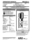
PUMP OPTION DESCRIPTION CHART
NM2328A - 1 1 - X 1 1
CONTAINER SUITABILITY
PLUNGER TYPE
SPRING ARRANGEMENT
CONTAINER SUITABILITY
1
UNIVERSAL (STUB)
SPRING ARRANGEMENT
1
COIL
PLUNGER TYPE
1
440 SERIESSTAINLESS STEEL
PACKING MATERIAL
PACKING MATERIAL
3
GLASS FILLEDPTFE (UPPERAND LOWER)
G UHMW-PE/ LEATHER STAG’D (UPPERAND LOWER)
S UHMW-PE /GLASS FILLEDPTFE STAG’D (UPPER
AND LOWER)
GENERAL DESCRIPTION
WARNING
HAZARDOUS PRESSURE. Do not exceed maxi-
mum operating pressure of 4200 p.s.i. (289.7 bar) at 150 p.s.i.
(10.3 bar) inlet air pressure.
PUMP RATIO X MAXIMUM PUMP
INLET PRESSURE TO PUMP MOTOR
= FLUID PRESSURE
Pump ratio is anexpression ofthe relationshipbetween thepump motorarea andthe
lowerpump endarea.EXAMPLE: When150 p.s.i.(10.3 bar)inletpressure issupplied
tothemotorofa28:1ratiopumpitwilldevelopamaximumof4200p.s.i.(289.7bar)fluid
pressure (at noflow) -- asthe fluid controlis opened, the flow rate willincrease asthe
motor cycle rate increases to keep upwith the demand.
WARNING
Refer to general information sheet for additional
safety precautions and important information.
Thetwo-balldesignprovidesforeasyprimingofthelowerfootvalve.
The double acting feature is standard in all ARO industrial pumps.
Materialisdeliveredtothe pumpdischargeoutletonboththeupand
down stroke.
The motor is connected to the lower pump end with a spacer tube
and solvent cup. This allows for lubrication of the upper packing
gland and to prevent air motor contamination because of normal
wear and eventual leakage through the material packing gland.
TROUBLE SHOOTING
Pump problems can occur in either the Air Motor Section or the Lower
Pump EndSection. Usethese basicguidelines tohelp determinewhich
section is affected. Be sure to eliminate any possible non-pump prob-
lems before suspecting pump malfunction.
Pump will not cycle.
No pressure to the motor. See motor manual.
Restricted return lines. Clean obstruction.
Damaged motor. Service motor
No material at the outlet (pump continually cycles).
Check the materialsupply, disconnect or shut off t he airsupply and
replenish the material, reconnect.
Material on one stroke only (fast downstroke).
The lower check may not be seating in the foot valve (see lower
pump disassembly). Remove the check from the foot valve, clean
and inspectthe valveseat area.If checkor footvalve aredamaged,
replace.
Material on one stroke only (fast upstroke).
The middle packings may be worn (see lower pump disassembly).
Replace the seals as necessary.
Material leakage out of the solvent cup or material appears on the
pump plunger rod.
Tightenthe solvent cupuntil leakagediscontinues. Ifthis procedure
does not aid in stopping the leakage problem, the upper packings
may be worn (see lower pump disassembly). Replace the seals as
necessary.
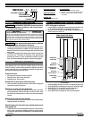
PUMP CONNECTION -- UPPER / LOWER
NOTE: All threads are right hand.
1. Loosen (90027) lock nut andunscrew entire pump from the air mo-
tor. This will expose (94786) connecting pin (see figure 2).
2. Remove (Y15-21-S) cotter pin and (94786) connecting pin to re-
lease plunger from piston rod.
Lower Pump
Plunger
Pump Motor
Piston Rod
Cotter Pin
(Y15-21-S) Ref.
PUMP CONNECTOR DETAIL
FIGURE 2
Connecting Pin
(94786) Ref.
Lock Nut
(90027) Ref.
REASSEMBLY
1. Assemble (90267) plunger to air motor rod, aligning through holes.
2. Assemble (94786) connecting pin through hole, securing plunger.
3. Assemble (Y15-21-S) cotter pin through connecting pin.
4. Screw the lower pump assembly to the air motor.
5. Screw (90027) lock nut against air motor base and tighten.