


PN 97999-1029
NM2202B-XPage2of2
PUMP OPTION DESCRIPTION CHART
NM2202B - X 1 - X 3 1
CONTAINER SUITABILITY
PLUNGER TYPE
SPRING ARRANGEMENT
CONTAINER SUITABILITY PACKING MATERIAL
1 - Universal (Stub) 7 - PTFE (upper and lower)
4 - 55 Gallon B - UHMW-PE (upper) / PTFE (lower)
C - UHMW-PE (upper and lower)
J - Polyurethane (upper) / UHMW-PE (lower)
SPRING ARRANGEMENT PLUNGER TYPE
3 - No Spring 1 - Standard (300 series Stainless steel)
PACKING MATERIAL
GENERAL DESCRIPTION
Model NM2202B-X Series two-ball, double acting pumps are intended
to be used primarily for oil transfer and delivery systems. It is best to use
this pump with low -- medium viscosity fluids. It uses Stainless steel and
other materials which make itcompatible with most petroleum based lu-
brication products. The two-ball design provides better priming of the
lowerfoot valve.Doubleacting pumpswill delivermaterialon boththeup
and down stroke.
NOTE: If this pump was purchased separately (not part of a system),
consult your sales representative for compatible dispensing accesso-
ries which will best match the application. All accessories must be able
to withstand the maximum pressure developed by the pump.
WARNING
HAZARDOUS PRESSURE. Do not exceed maxi -
mumoperating pressureof351p.s.i. (24.2bar)at150 p.s.i.(10.3
bar) inlet air pressure.
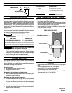
PUMP RATIO X MAXIMUM PUMP
INLET PRESSURE TO PUMP MOTOR
= FLUID PRESSURE
Pump ratio is an expression of the relationship between the pump motor area and the
lower pumpend area. EXAMPLE: When150 p.s.i. (10.3 bar) inlet pressure is supplied
to the motor of a 4:1 ratio pump it will develop a maximum of 600 p.s.i. (41.4 bar) fluid
pressure (at no flow) - as the fluid control is opened, the flow rate will increase as the
motor cycle rate increases to keep up with the demand.
WARNING
Refer to general information sheet for additional
safety precautions and important information.
NOTICE: Thermal expansion can occur whenthe fluid inthe materi-
al lines is exposed to elevated temperatures. Example: Material
lines located in a non-insulated roof area can warm due to sunlight.
Install a pressure relief valve in the pumping system.
Replacement warning label (pn 94520) is available upon request.
TROUBLE SHOOTING
Pump problems can occur in either the Air Motor Section or the Lower
Pump End Section. Use these basic guidelines to help determine which
section is affected. Be sure to eliminate any possible non-pump prob-
lems before suspecting pump malfunction.
Pump will not cycle.
• No pressure to the motor. See motor manual.
• Damaged motor. Service motor
No material at the outlet (pump continually cycles).
• Check the material supply, disconnect or shut off the air supply and
replenish the material, reconnect.
Material on one stroke only (fast downstroke).
• The lower check may not be seating in the foot valve (see lower
pump disassembly). Remove the check from the foot valve, clean
and inspect the valve seat area. If check or foot valve are damaged,
replace.
Material on one stroke only (fast upstroke).
• The middle packings may be worn (see lower pump disassembly).
Replace the seals as necessary.
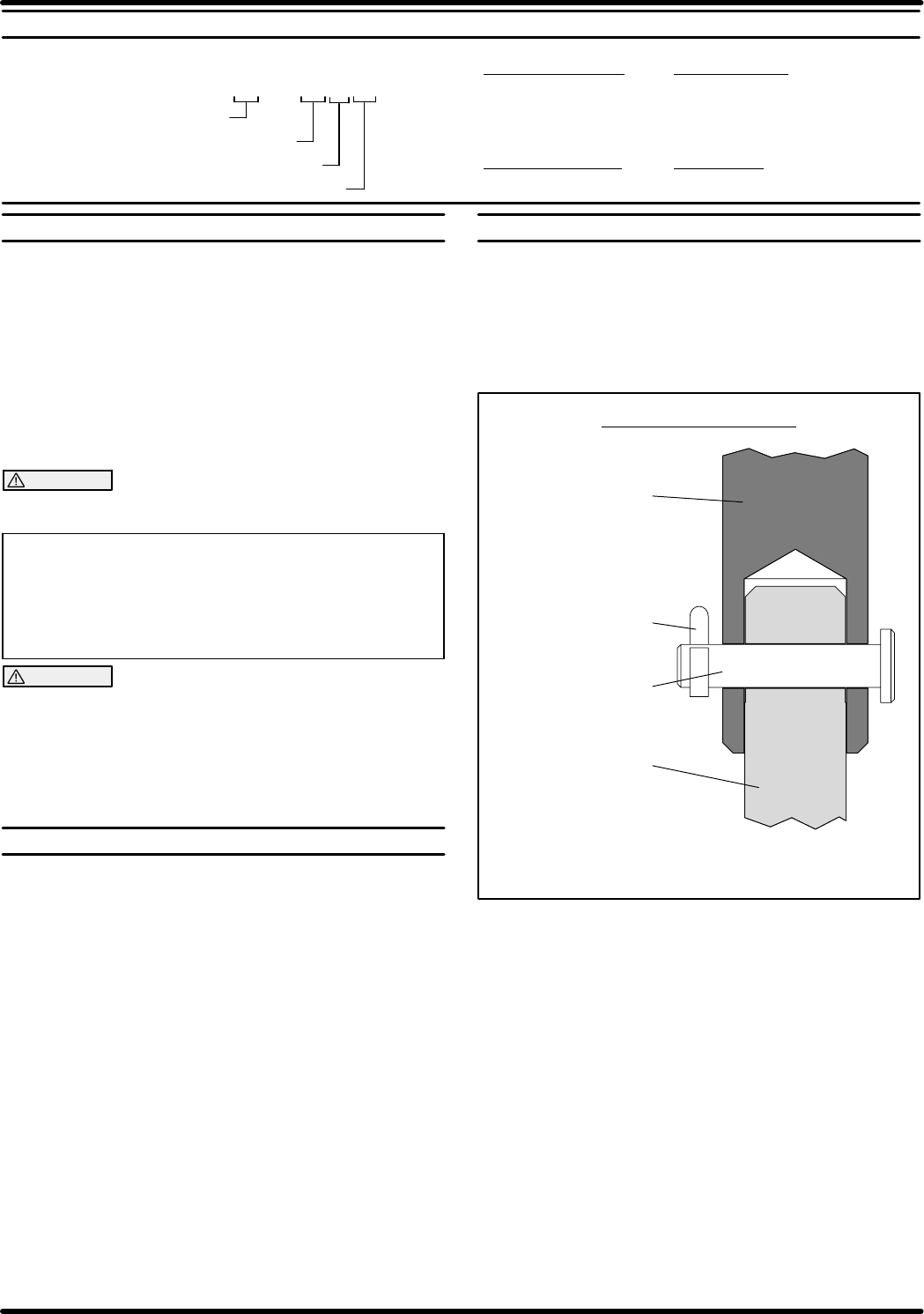
PUMP CONNECTION - UPPER / LOWER
NOTE: All threads are right hand.
1. Lay the pump assembly on a workbench.
2. Remove four (Y99-41-C) cap screws and pull the air motor from the
lower pump end until the motor piston rod is in the “down” position
and the lower pump end rod is in the “up” position.
3. Removethe (Y15-31-C) cotter pin and(96064) pin, releasing the air
motor from the lower pump end.
Lower Pump Rod
Pump Motor Piston Rod
Cotter Pin Y15-31-C
PUMP CONNECTOR DETAIL
Figure 2
Pin 96064
REASSEMBLY
1. Assemble motor piston rod to the lower pump end rod, aligning thru
holes.
2. Assemble (96064) pin through hole, securing rods.
3. Assemble (Y15-31-C) cotter pin through hole in pin.
4. Align tie rods with holes in pump outlet body.
5. Assemble four (Y99-41-C) cap screws, securing air motor. NOTE:
Tighten cap screws to 50 in. lbs (5.65 Nm).