


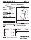
LP2003-X
PAGE2OF2
PN97999-697
PLACING INT
O SER
VICE
OPERA
TING AND SAFETY PRECAUTIONS
WARNING READ THE GENERAL INFORMATION MANUAL
INCLUDED FOR OPERATING AND SAFETY PRECAUTIONS
AND OTHER IMPORTANT INFORMATION.
WARNING EXCESSIVE INLET PRESSURE. Can cause exĆ
plosion resulting in severe injury or death. Do not exceed
maximum operating pressure of 7500 psi (517 bar) at 125 psi
(8.6 bar) inlet air pressure. Do not run pump without using a
regulator to limit air supply pressure to the pump.
PUMP RATIO X
INLETPRESSURETO PUMPMOTOR
=
MAXIMUMPUMP
FLUIDPRESSURE
Pumpratiois anexpressionoftherelationshipbetweenthepumpmotorareaand
the lower pumpend area. EXAMPLE:When 125p.s.i. (8.6 bar)inlet pressure is
suppliedtothemotor ofa 60:1ratiopumpitwilldevelopamaximumof7500p.s.i.
(517 bar)fluid pressure(at noflow) - as thefluid control isopened, theflow rate
will increase as themotor cycle rate increases to keepup with the demand.
WARNING EXCESSIVE MATERIAL PRESSURE. Can cause
equipment failure resulting in severe injury or property
damage. Do not exceed the maximum material pressure
handling capability of any component in the system.
Thermal expansion hazard. This can occur when the fluid in the
material line is exposed to elevated temperatures.
Example: Material line located in a non-insulated roof area can
warm due to sunlight. Install a pressure relief valve in thepumping
system if this condition could exist.
AIR AND LUBRICATION REQUIREMENTS
Filtered air will help extend the life of the pump, allowing the pump to
operate moreefficientlyand yieldlonger servicelifetomovingpartsand
mechanisms.
• Use an air linefilter to provide goodquality clean and dryair, install
it up stream from the air regulator.
• Use anair regulatoronthe airsupply tocontrol thepumpcycle rate,
install the regulator as close as possible to the pump.
• In mostinstallations lubricationis notrequired. Ifthepumpneedsto
have lubrication, install an airline lubricator betweenthe pumpand
the air regulator and supply it with a good grade of non-detergent
oil or other lubricant compatible with Buna``N'' seals.
Set at a rate not to exceed one drop per minute.
INSTALLATION
Assemble components included in the package as shown in the Fig.1.
NOTE: In rigid plumbing applications, use flexible material and air
supply hoseswhenattaching thepumpto preventdamageby vibration.
1. Thread the pump bung adapter into the pump cover, insert the
pump into the bung and then secure with the thumb screws
provided.
2. Install the outlet adapter, material hose, swivel and gun.
3. Lay the follower on top of a full bucket of grease, feed the lower
pump end into the follower and secure the cover with the thumb
screws.
4. Attach the coupler to the air supply hose.
5. Connect the material hose to the pump outlet. Tighten all fittings.
Use caution not to damage threads.
OPERATION
START-UP
1. Turn the airregulator to ``0'' pressure setting. Connect the air hose.
2. Prime thepumpby cyclingslowly, raisingthepressure to20-30psi.
Cycle the pump until the test grease and any trapped air has been
purged from the system.
3. Close the dispensing device. Allow thepump to build line pressure
and stall. Check for any leaks and re-torque fittings if needed.
Adjust air pressure upward as required for the application.
NOTICE: If the pump does not prime soon after initial start-up,
establish what the problem is to prevent unnecessary damage to the
pump plunger.
SHUTDOWN
• Disconnect the air supply from the pump if it is to be inactive for a
few hours. Open the dispensing device to relieve line pressure.
SERVICE
Refer to the basic pump manual for service instructions which also
covers disassembly and reassembly for installation of the rebuild kit.
TROUBLE SHOOTING
If the pump does not cycle or will not deliver material.
• Be certain to check for non-pump problems including kinked,
restrictive or plugged inlet/outlet hose or dispensing device.
Depressurize the pump system and clean out any obstructions in
the inlet/outlet material lines.
• Check all seals, including track gaskets.