


LM2305A-X-B
Page4of4
OPERATING AND SAFETY PRECAUTIONS
WARNING
READ THE GENERAL INFORMATION MANUAL
INCLUDED FOR ADDITIONAL OPERATING AND SAFETY PRE-
CAUTIONS AND OTHER IMPORTANT INFORMATION.
WARNING
EXCESSIVE INLET PRESSURE. Can cause ex-
plosion resulting insevereinjury ordeath. Donot exceedmaxi-
mumoperating pressureof750 p.s.i.(51.7 bar)at 150p.s.i.(10.3
bar) inletair pressure. Donot run pumpwithout using aregula-
tor to limit air supply pressure to the pump.
WARNING
EXCESSIVE MATERIAL PRESSURE. Can cause
equipment failure resulting in severe injury or property dam-
age. Do not exceed the maximum material pressure of any
component in the system.
PUMP RATIO X
INLET PRESSURE TO PUMP MOTOR
=
MAXIMUM PUMP
FLUID PRESSURE
Pump ratio isan expressionof therelationship between thepump motor areaand
the lower pumpend area. EXAMPLE: When150 p.s.i. (10.3 bar)inlet pressure is
supplied to the motor of a 5:1 ratio pump it will develop a maximum of 750 p.s.i.
(51.7 bar) fluid pressure (at no flow) -- as the fluid controlis opened, the flow rate
will increase as the motor cycle rate increases to keep up with the demand.
NOTICE: Thermal expansioncan occur whenthe fluid in themateri-
al lines is exposed to elevated temperatures. Example: Material
lines located in a non-insulated roof area can warm due to sunlight.
Install a pressure relief valve in the pumping system.
Replacement warning label (pn 94520) is available upon request.
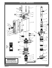
PUMP DISASSEMBLY
NOTE: Allthreads are righthand. Referto figure2 (page3). Discon-
nect air supply and relieve all system pressure
prior to servicing.
Carefully removethe parts,inspect fordamage, nicksor excessive wear
and determine if any parts will need replacement.
1. Using a 7/8” wrench, unthread and remove (12) adapter and (11 and
13) “O” rings, r eleasing ( 15) muf fler housing.
2. Using a 7/16” wrench, remove (36) nuts.
3. Remove four (1) bolts, (2) upper cap and (3) gasket.
4. Remove (10) cylinder, containing (4) sleeves and (7) spools.
5. Using (1) bolt, push (7) spools and (4) sleeves out “sleeve” end of
(10) cylinder.
6. Pull up on (21) piston and (22) lower c ap, allowing access to (25)
bushing.
7. Using a 1-5/8” wrench, unthread (25) bushing and pull (28) piston
rod and components from pump.
8. Clamp onflats of(28) pistonrod in avise. Usingan 11/16” wrench on
flats of (30) cup follower, unthread and remove from (28) piston rod.
9. Clamp on flats of (30) cup follower in a vise. Using a 1-1/2” wrench,
unthread and remove (34) inner check seat, releasing (32) washer,
(33) ball and (31) piston cup.
10. Remove (25) bushing from (28) piston rod.
11. Remove (24) “O” ring and (26) packing from (25) bushing.
PUMP REASSEMBLY
NOTE: Thoroughly clean and lubricate all seals. Replace all soft
parts with new ones included in the repair kit. Note: Refer to the il-
lustration (figure 2, page 3) for “U” cup lip seal direction.
1. Replace (27) “O” ring on (28) piston rod.
2. Replace (20) “U” cups on (21) piston and assemble (21) piston onto
(28) piston rod, securing with (19) washer and (18) retaining ring.
3. Assemble (3) gasket to (22) lower cap and assemble(22) lower cap
and (23) “O” ring onto (28) piston rod.
4. Assemble (33) balland (31) pistoncup to (30)cup follower, securing
with (32) washer and (34) inner check seat.
5. Replace (26) packing in (25) bushing.
6. Replace (24) “O” ring on (25) bushing and assemble (25) bushing
onto (28) piston rod.
7. Clamp on flats of (28) piston rod in a vise.
8. Assemble (29) rod and (30) cup follower to (28) piston rod andtight-
en byusing a 1-1/2” wrench on(34) inner check.NOTE: Torque (34)
check seat to 65 ft lbs (88.1 Nm).
9. Clamp (39) tube horizontally in a vise.
10. Assemble (28) piston rod and components into (35) base.
11. Using a 1-5/8” wrench, thread (25) bushing into (35) base until it
“bottoms”. NOTE: Be careful not to raise any burrs on flats of (25)
bushing.
12. Replace (5) “O” rings on (4) sleeves and assemble (4) sleeves into
(10) cylinder.NOTE: Assemble eachsleeve intothe endof the cylin-
der nearest the exhaust hole.
13. Replace (6 and 9) “O” rings and (8) “U” cups on (7) spools and as-
semble (7) spools into (10) cylinder from the opposite end as the (4)
sleeve went in.
14. Assemble (10) cylinder onto the pump, being careful when sliding
over the lips of (20) “U” cups. NOTE: Be sure (3) gasket is seated
properly.
15. Replace (3) gasket on (2) upper cap and assemble (2) upper cap to
(10) cylinder.
16. Assemble(1) bolts to pump, securing with (36) nuts. NOTE: Torque
(36) nuts evenly to 80 in. lbs (9 Nm).
17. Replace (11 and 13) “O” rings on (12) adapter.
18. Assemble(16) foam liners and (17) edge trims to (15) muffler hous-
ing.
19. Assemble (15) muffler housing to (10) cylinder, securing w ith (12)
adapter. NOTE: Torque (12) adapter to 80 in. lbs (9 Nm).
TROUBLE SHOOTING
If the pump will not cycle or will not deliver material.
• Becertain tocheck fornon-pump problemsincluding kinked,restric-
tiveor pluggedinlet /outlet hoseor dispensingdevice. Depressurize
the pump system and clean out any obstructions in the inlet / outlet
material lines.
• Check all seals, including track gaskets.
• Check direction of “U” cup lips.
PN 97999-1134