


OPERATING AND SAFETY PRECAUTIONS
WARNING
WARNING
WARNING
Pump ratio is an expression of the relationship between the pump motor area and
the lower pump end area. EXAMPLE: When 150 p.s.i. (10.3 bar) inlet pressure is
supplied to the motor of a 5:1 ratio pump it will develop a maximum of 750 p.s.i.
(51.7 bar) fluid pressure (at no flow) - as the fluid control is opened, the flow rate
will increase as the motor cycle rate increases to keep up with the demand.
NOTICE: Thermal expansion can occur when the fluid in the materiĆ
al lines is exposed to elevated temperatures. Example: Material
lines located in a nonĆinsulated roof area can warm due to sunlight.
Install a pressure relief valve in the pumping system.
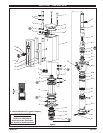
PUMP DISASSEMBLY
Carefully remove the parts, inspect for damage, nicks or excessive wear
and determine if any parts will need replacement.
1. Using a 7/8" wrench, unthread and remove (12) adapter and (11 and
13) O" rings, releasing (15) muffler housing.
2. Using a 7/16" wrench, remove (36) nuts.
3. Remove four (1) bolts, (2) upper cap and (3) gasket.
4. Remove (10) cylinder, containing (4) sleeves and (7) spools.
5. Using (1) bolt, push (7) spools and (4) sleeves out sleeve" end of
(10) cylinder.
6. Pull up on (21) piston and (22) lower cap, allowing access to (25)
bushing.
7. Using a 1Ć5/8" wrench, unthread (25) bushing and pull (28) piston
rod and components from pump.
8. Clamp on flats of (28) piston rod in a vise. Using an 11/16" wrench on
flats of (30) cup follower, unthread and remove from (28) piston rod.
9. Clamp on flats of (30) cup follower in a vise. Using a 1Ć1/2" wrench,
unthread and remove (34) inner check seat, releasing (32) washer,
(33) ball and (31) piston cup.
10. Remove (25) bushing from (28) piston rod.
11. Remove (24) O" ring and (26) packing from (25) bushing.
PUMP REASSEMBLY
Note: Refer to the ilĆ
lustration (figure 2, page 3) for U" cup lip seal direction.
1. Replace (27) O" ring on (28) piston rod.
2. Replace (20) U" cups on (21) piston and assemble (21) piston onto
(28) piston rod, securing with (19) washer and (18) retaining ring.
3. Assemble (3) gasket to (22) lower cap and assemble (22) lower cap
and (23) O" ring onto (28) piston rod.
4. Assemble (33) ball and (31) piston cup to (30) cup follower, securing
with (32) washer and (34) inner check seat.
5. Replace (26) packing in (25) bushing.
6. Replace (24) O" ring on (25) bushing and assemble (25) bushing
onto (28) piston rod.
7. Clamp on flats of (28) piston rod in a vise.
8. Assemble (29) rod and (30) cup follower to (28) piston rod and tightĆ
en by using a 1Ć1/2" wrench on (34) inner check. NOTE: Torque (34)
check seat to 65 ft lbs (88.1 Nm).
9. Clamp (39) tube horizontally in a vise.
10. Assemble (28) piston rod and components into (35) base.
11. Using a 1Ć5/8" wrench, thread (25) bushing into (35) base until it
bottoms". NOTE: Be careful not to raise any burrs on flats of (25)
bushing.
12. Replace (5) O" rings on (4) sleeves and assemble (4) sleeves into
(10) cylinder. NOTE: Assemble each sleeve into the end of the cylinĆ
der nearest the exhaust hole.
13. Replace (6 and 9) O" rings and (8) U" cups on (7) spools and asĆ
semble (7) spools into (10) cylinder from the opposite end as the (4)
sleeve went in.
14. Assemble (10) cylinder onto the pump, being careful when sliding
over the lips of (20) U" cups. NOTE: Be sure (3) gasket is seated
properly.
15. Replace (3) gasket on (2) upper cap and assemble (2) upper cap to
(10) cylinder.
16. Assemble (1) bolts to pump, securing with (36) nuts. NOTE: Torque
(36) nuts evenly to 80 in. lbs (9 Nm).
17. Replace (11 and 13) O" rings on (12) adapter.
18. Assemble (16) foam liners and (17) edge trims to (15) muffler housĆ
ing.
19. Assemble (15) muffler housing to (10) cylinder, securing with (12)
adapter. NOTE: Torque (12) adapter to 80 in. lbs (9 Nm).
TROUBLE SHOOTING
• Be certain to check for nonĆpump problems including kinked, restricĆ
tive or plugged inlet / outlet hose or dispensing device. Depressurize
the pump system and clean out any obstructions in the inlet / outlet
material lines.
• Check all seals, including track gaskets.
• Check direction of U" cup lips.