


LM2203A-X-C4Page2of4
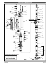
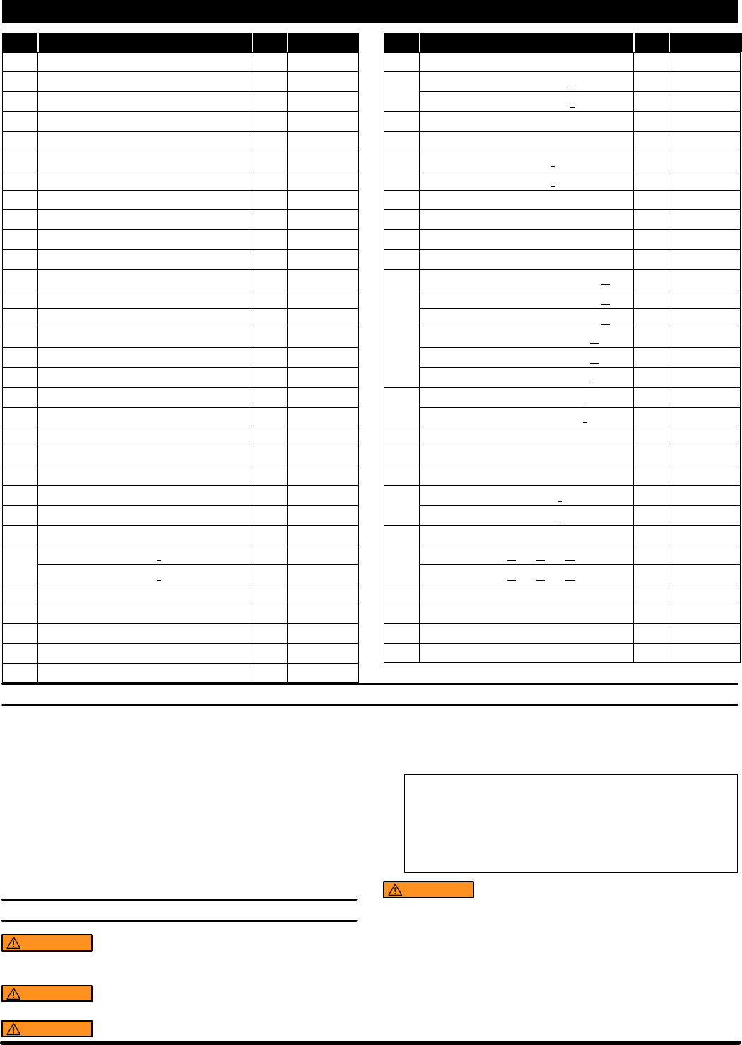
PARTS LIST / LM2203A-XX-C4
Item Description (size) (Qty) Part No. Item Description(size) (Qty) Part No.
1 Bolt (4) 94333
2 Upper Cap (1) 94307
n 3 Track Gasket (2) 94311
4 Sleeve (2) 94316
n 5 “O” Ring (1/16” x 11/16” o.d.) (4) Y325-15
n 6 “O” Ring (1/8” x 3/4”o.d.) (4) Y325-206
7 Spool (2) 94310
n 8 “U” Cup (1/8” x 3/4”o.d.) (2) Y240-7
n 9 “O” Ring (0.106” x 0.587”o.d.) (2) 15066-PM
10 Muffler Housing (1) 94443
11 Cylinder (1) 94249
12 Retaining Ring (1) 94406
n 13 “U” Cup (3/16” x2” o.d.) (2) Y240-23
14 Piston (1) 94780
15 Lower Cap (1) 94308
n 16 “O” Ring (1/8” x1-3/8” o.d.) (1) Y325-216
17 Bushing (1) 94332
n 18 Packing (1/4” x1-5/8” o.d.) (1) 97181
n 19 “O” Ring (3/32” x 1”o.d.) (1) Y325-117
20 Piston Rod (1) 94779
21 Groove Pin (3/16” o.d.x 1-1/8” long) (1) 94338
22 Spring (1) 94705
23 Ball (3/4” dia.) (1) Y16-224
24 Inner Check (1) 94279
n 25 “O” Ring (3/16” x 1-7/16”o.d.) (1) Y327-319
26 Base -models LM2203A-( )1-C4 (1) 96253
-models LM2203A-( )2-C4 (1) 96253-1
27 Nut (4) 93828
n 28 Copper Gasket (1) 96031
29 Tube (1) 94314-1
n 30 “O” Ring (3/32” x 1-9/16”o.d.) (1) Y327-126
31 Ball (1” dia.) (1) Y16-232
32 Ball Stop Pin (0.187” dia. x 1.430” long) (1) 94339
33 Foot Valve - modelsLM2203A-( )1-C4 (1) 94315
-models LM2203A-( )2-C4 (1) 94315-1
n 34 “O” Ring (1/16” x 7/16”o.d.) (1) Y325-11
n 35 “O” Ring (1/16” x 3/4”o.d.) (1) Y325-16
36 Adapter -models LM2203A-( )1-C4 (1) 94447
-models LM2203A-( )2-C4 (1) 94447-1
37 Foam Liner (2) 94402
38 Ground Screw (#10 -32 x 1/4”) (1) 93005
39 Bung Assembly (includes items40 and 49) (1) 67145-3-B
40 Thumb Screw (1/4” -20 x 1-1/2”) (1) Y197-158-C
41 Pipe Extension -models LM2203A-31-C4 (1) 94523-3
3/4 -14 N.P.T.x 30-1/8” -models LM2203A-41-C4 (1) 94523-4
3/4 -14 N.P.T.x 37-3/4” -models LM2203A-51-C4 (1) 94523-5
Rc 3/4(3/4 -14 BSPtaper x20-3/8”) -LM2203A-32-C4 (1) 94537-3
Rc 3/4(3/4 -14 BSPtaper x30-1/8”) -LM2203A-42-C4 (1) 94537-4
Rc 3/4(3/4 -14 BSPtaper x37-3/4”) -LM2203A-52-C4 (1) 94537-5
42 Valve Housing -models LM2203A-( )1-C4 (1) 94535
-models LM2203A-( )2-C4 (1) 94535-1
43 Ball Guide (1) 77904
44 Ball (1” dia.) (1) Y16-232
n 45 “O” Ring (3/32” x 1-7/16”o.d.) (1) Y325-124
46 Ball Seat - modelsLM2203A-( )1-C4 (1) 94534
-models LM2203A-( )2-C4 (1) 94534-1
47 Valve Assembly (includes items42 thru 46)
models LM2203A-31-C4, -41-C4, -51-C4 (1) 67085
models LM2203A-32-C4, -42-C4, -52-C4 (1) 67085-1
48 Washer (1) 94515
49 Nut (1/4” - 20) (1) Y12-4-C
n (1) 94833
n Parts in Repair Kit 637481
GENERAL DESCRIPTION
Model LM2203A-X-C4 series two-ball double acting pumps are in-
tendedtobeusedprimarilyforoiltransferanddeliverysystems.Itisbest
to use this pump withlow -- mediumviscosity fluids. Ituses carbon steel
and other materials which make it compatible with most petroleum
based lubrication products.The two-ball designprovides better priming
ofthe lower footvalve. Doubleacting pumpswilldelivermaterialon both
the up and down stroke.
NOTE: If this pump was purchased separately (not part of a system),
consult your sales representative for compatible dispensing accesso-
ries which will best match the application. All accessories must be able
to withstand the maximum pressure developed by the pump.
OPERATING AND SAFETY PRECAUTIONS
WARNING
READ THE GENERAL INFORMATION MANUAL
INCLUDEDFOR ADDITIONALOPERATINGAND SAFETYPRE-
CAUTIONS AND OTHER IMPORTANT INFORMATION.
WARNING
STATIC SPARK. Can cause explosion resulting in
severe injury or death. Ground the pump and pumping system.
WARNING
EXCESSIVE INLET PRESSURE. Can cause ex-
plosionresultinginsevereinjuryordeath.Donotexceedmaxi-
mumoperatingpressureof450p.s.i.(31.0bar)at150p.s.i.(10.3
bar)inletair pressure.Donot runpumpwithoutusing aregula-
tor to limit air supply pressure to the pump.
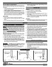
PUMP RATIO X
INLET PRESSURE TO PUMP MOTOR
=
MAXIMUM PUMP
FLUID PRESSURE
Pumpratioisanexpressionoftherelationship betweenthepumpmotor areaand
thelower pumpend area.EXAMPLE: When150p.s.i. (10.3bar) inletpressure is
supplied to the motor of a 3:1 ratio pump it will develop a maximum of 450 p.s.i.
(31.0 bar)fluid pressure (atno flow) -- as thefluid controlis opened,the flow rate
will increase as the motor cycle rate increases to keep up with the demand.
WARNING
EXCESSIVE MATERIAL PRESSURE. Can cause
equipment f ailureresulting insevere injuryor property damage.
Do not exceed the maximum material pressure of any compo-
nent in the system.
NOTICE:Thermal expansioncan occurwhenthe fluidin themateri-
al lines is exposed to elevated temperatures. Example: Material
lines located in a non-insulated roof area can warm due to sunlight.
Install a pressure relief valve in the pumping system.
Replacement warning label (pn 94520) is available upon request.
Gadus S2 U1000 Grease Packet