


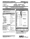
PN 97999-1132
LM2203A-X-CPage4of4
PLACING INTO SERVICE
AIR AND LUBRICATION REQUIREMENTS
Filtered air will help extend thelife of the pump, allowing the pump to op-
erate more efficiently and yield longer service life to moving parts and
mechanisms.
• Install an air linefilter toprovidegood qualityclean and dryair. Install
it up stream from the regulator.
• Use an air regulator on the air supply to control the pump cycle rate.
Install the regulator as close as possible to the pump.
• In mostinstallations, lubrication isnot required. If thepump needs to
have lubrication, install an air linelubricator andsupply itwith a good
grade of non-detergent oil or other lubricant compatible with Nitrile
seals and set at a rate not to exceed one drop per minute.
INSTALLATION
• Mount and secure the pump as required for the application.
• Attach a ground wire from the pump ground screw to a suitable
ground.
• Connect afluid hoseto the pumpoutlet. Inmost casesa pipesealant
should be used on thread connection. Tighten all fittings. Use cau-
tion not to damage threads.
OPERATION
START-UP
1. Turn the air regulator to “0” pressure setting.
2. Immerse the lower pump end into the material.
3. Open the dispensing device.
4. Start the pump cycling slowly by raising the pressure to 20 - 30p.s.i.
(1.4 - 2.1 bar).
5. Close the dispensing device. Allow the pump to stall and build line
pressure. Check for any leaks and tighten fittings as needed.Adjust
pressure as required for the application.
SHUTDOWN
• Disconnect theair supply from thepump if it isto be inactivefor a few
hours. Open the dispensing device to relieve line pressure.
SER VICE
PUMP DISASSEMBLY / REASSEMBLY
NOTICE: The unique design of this pump allows for quick basic pump
service without total removal from the drum (refer to the views below).
DISASSEMBLY
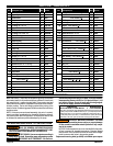
- Allthreads areright hand.Refer tofigure 2.These
proceduresare fortheinstallation ofrepairkitparts. Disconnectair
supply and relieve all system pressure
prior to servicing. Carefully
remove theparts, inspect partsfor damage,nicks orexcessive wearand
determine if any parts will need replacement.
Follow the three disassembly steps in the detail views below and place
the pump on a clean bench.
1. Remove (1) bolts. Remove (18) packing,(17) bushing and (16) “O” ring.
2. Remove (36) adapter, releasing (10) muffler housing.
3. Grasp the (11) cylinder and remove the (20, 14) piston assembly.
4. Remove(15) lower cap and (3) track gasket. Remove (12) retaining
ring and (48) washer, then pull (14) piston off (20) piston rod.
5. Remove (2) cap and (3) track gasket. Push on the large o.d. end of
the (7) spoolto removethe (4)sleeve. Grabthe noseof (7) spooland
pull out. Repeat for other sleeve and spool.
REASSEMBLY
- Thoroughly clean and lubricate all seals and
bores with Shell Gadus S2 U1000 upon assembly. Replace all soft
parts with new ones included in the repair kit.
Note: Refer to the illustration (figure 2) for “U” cup lip seal direction.
1. Replace the seals on both the (7) spools and (4) sleeves.
2. Locate the valve chamber on the (11) cylinder where the 3/8’’ dia.
hole is located and install one of the (4) sleeves. Insert the (7) spool
from the opposite end. Next, install the remaining sleeve and spool.
3. Replace the (3) track gasket and install (2) cap.
4. Replacethe (13) piston “U” cups (refer to figure 2for proper orienta-
tion). Replace the (19) “O” ring and assemble (14) piston to(20) pis-
ton rod and retain with (48) washer and (12) retaining ring.
5. Install the (20, 14) piston assembly using great care to collapse the
outer lip of the second “U” cup, allowing it to slip into the cylinder.
6. Replace the (3) track gasket and install the (15) cap. Install the (16)
“O” ring onto the piston rod, replace (17) bushing and (18) packing.
7. Replace the (25) “O” ring and re-attach the (24) inner check.
8. Slide the pump assembly back into the (26) base / lower pump sec-
tion. Pressthe sectionstogether andalignthe airinlet andpump out-
let as required and replace the four(1) bolts and (27) nuts(tighten to
80 in. lbs (9 Nm).
TROUBLE SHOOTING
If the pump will not cycle or will not deliver material.
• Be certainto check fornon-pump problemsincluding kinked,restric-
tive orplugged inlet/ outlethose ordispensing device.Depressurize
the pump system and clean out any obstructions in the inlet / outlet
material lines.
• Check all seals, including track gaskets.
• Check direction of “U” cup lips.
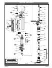
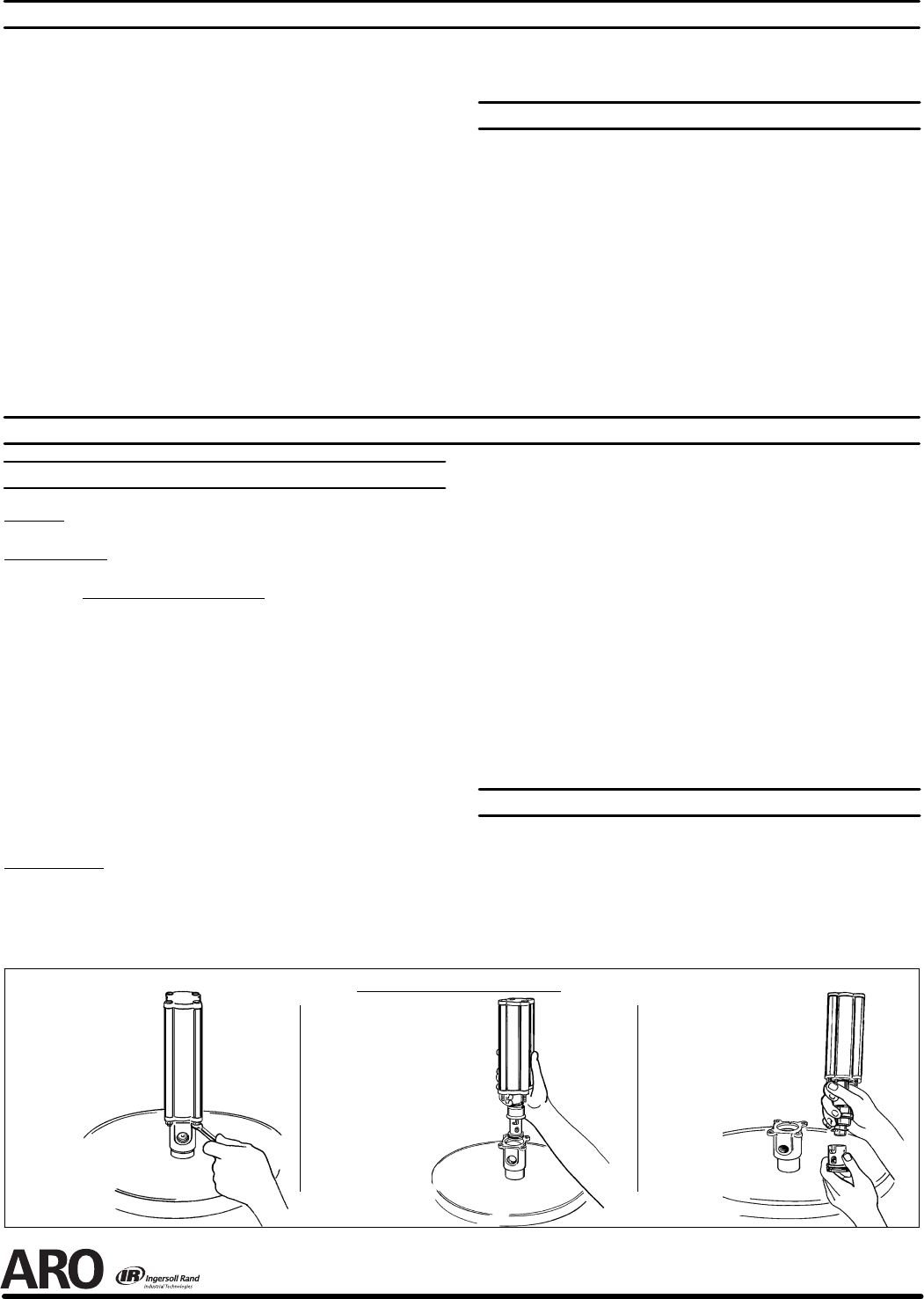
C) Unlock the (24) inner
check from the piston
rod.
Figure 5
Figure 4
B) Grasp the lower motor cap
and pull out the motor and
upper section of the lower
section.
PUMP DISASSEMBLY DETAIL
Figure 3
A) Remove the four
nuts from the base
of the Air Motor.