


PLACING INTO SERVICE
Filtered air will help extend the life of the pump, allowing the pump to opĆ
erate more efficiently and yield longer service life to moving parts and
mechanisms.
• Install an air line filter to provide good quality clean and dry air. Install
it up stream from the regulator.
• Use an air regulator on the air supply to control the pump cycle rate.
Install the regulator as close as possible to the pump.
• In most installations, lubrication is not required. If the pump needs to
have lubrication, install an air line lubricator and supply it with a good
grade of nonĆdetergent oil or other lubricant compatible with Nitrile
seals and set at a rate not to exceed one drop per minute.
• Mount and secure the pump as required for the application.
• Attach a ground wire from the pump ground screw to a suitable
ground.
• Connect a fluid hose to the pump outlet. In most cases a pipe sealant
should be used on thread connection. Tighten all fittings. Use cauĆ
tion not to damage threads.
OPERATION
1. Turn the air regulator to 0" pressure setting.
2. Immerse the lower pump end into the material.
3. Open the dispensing device.
4. Start the pump cycling slowly by raising the pressure to 20 Ć 30 p.s.i.
(1.4 Ć 2.1 bar).
5. Close the dispensing device. Allow the pump to stall and build line
pressure. Check for any leaks and tighten fittings as needed. Adjust
pressure as required for the application.
• Disconnect the air supply from the pump if it is to be inactive for a few
hours. Open the dispensing device to relieve line pressure.
SERVICE
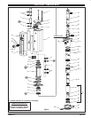
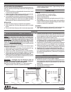
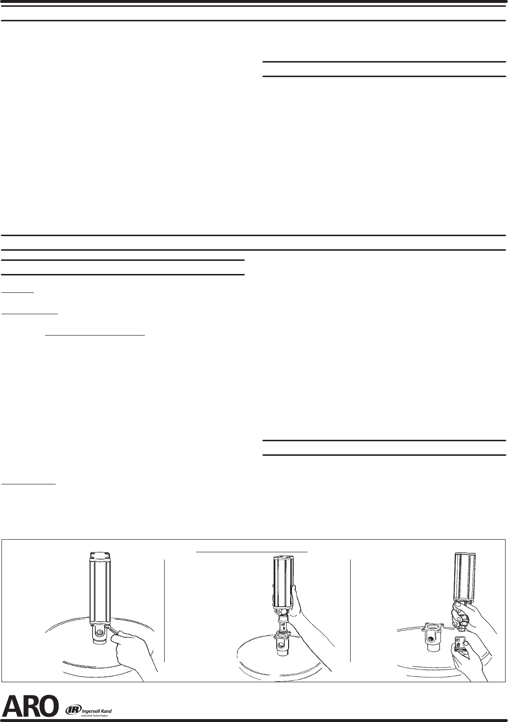
PUMP DISASSEMBLY / REASSEMBLY
The unique design of this pump allows for quick basic pump
service without total removal from the drum (refer to the views below).
Carefully
remove the parts, inspect parts for damage, nicks or excessive wear and
determine if any parts will need replacement.
Follow the three disassembly steps in the detail views below and place
the pump on a clean bench.
1. Remove (1) bolts. Remove (18) packing, (17) bushing and (16) O" ring.
2. Remove (36) adapter, releasing (10) muffler housing.
3. Grasp the (11) cylinder and remove the (20, 14) piston assembly.
4. Remove (15) lower cap and (3) track gasket. Remove (12) retaining
ring and (48) washer, then pull (14) piston off (20) piston rod.
5. Remove (2) cap and (3) track gasket. Push on the large o.d. end of
the (7) spool to remove the (4) sleeve. Grab the nose of (7) spool and
pull out. Repeat for other sleeve and spool.
Note: Refer to the illustration (figure 2) for U" cup lip seal direction.
1. Replace the seals on both the (7) spools and (4) sleeves.
2. Locate the valve chamber on the (11) cylinder where the 3/8'' dia.
hole is located and install one of the (4) sleeves. Insert the (7) spool
from the opposite end. Next, install the remaining sleeve and spool.
3. Replace the (3) track gasket and install (2) cap.
4. Replace the (13) piston U" cups (refer to figure 2 for proper orientaĆ
tion). Replace the (19) O" ring and assemble (14) piston to (20) pisĆ
ton rod and retain with (48) washer and (12) retaining ring.
5. Install the (20, 14) piston assembly using great care to collapse the
outer lip of the second U" cup, allowing it to slip into the cylinder.
6. Replace the (3) track gasket and install the (15) cap. Install the (16)
O" ring onto the piston rod, replace (17) bushing and (18) packing.
7. Replace the (25) O" ring and reĆattach the (24) inner check.
8. Slide the pump assembly back into the (26) base / lower pump secĆ
tion. Press the sections together and align the air inlet and pump outĆ
let as required and replace the four (1) bolts and (27) nuts (tighten to
80 in. lbs (9 Nm).
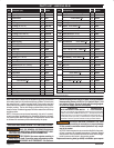
TROUBLE SHOOTING
• Be certain to check for nonĆpump problems including kinked, restricĆ
tive or plugged inlet / outlet hose or dispensing device. Depressurize
the pump system and clean out any obstructions in the inlet / outlet
material lines.
• Check all seals, including track gaskets.
• Check direction of U" cup lips.
C) Unlock the (24) inner
check from the piston
rod.
B) Grasp the lower motor cap
and pull out the motor and
upper section of the lower
section.
A) Remove the four
nuts from the base
of the Air Motor.
Gadus S2 U1000