Page 2 of 4 67442
CAUTION
High pressure equipment – Always
disconnect air supply and relieve material pressure
before attempting to service.
Ball Valve
Move the (8) control handle counterclockwise to pres-
surize the system. A 90 degree movement would be the
“o ” position. A 90 – 180 degree movement would allow
the system to be throttled to full regulated line pressure
(180 degree counterclockwise position being the “on”
position) .
2. Move the (8) control handle clockwise to either stop
the system or to de-pressurize the system. A 90 degree
movement would return to the “off” position. A 90 –
180 degree movement would allow the system to be
de-pressurized and vent the residual system pressure
through the (6) vent nut and dump to atmosphere (180
degree clockwise position being “vent” position).
1.
OPERATING AND SAFETY PRECAUTIONS
INSTALLATION
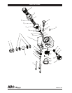
Install the 67442 self- relieving ball valve regulator us-
ing the three (11) bolts passing through the (1) regulator
housing. Be certain that the (26) O-ring is in the recess
groove on the mounting side of the (1) regulator hous-
ing to establish the pneumatic seal. Tighten all (11) bolts
evenly to 50-60 in-lbs (13.6-20.3 Nm)
.
The (39) adjustment knob should be turned counter-
clockwise until compression is released from the pressure
control spring. This prevents over pressurizing the air op-
erated equipment when the air supply is turned on .
The (8) ball valve control handle should be turned clock-
wise until it stops. This will be in the de-pressurize / vent
position of the control handle. The (8) handle position is
adjustabe to eight di erent locations and can be adjust-
ed by removing the (10) button head screw, (9) washer,
and (8) control handle and oriented as desired. The (7)
key should not be removed. The (7) key establishes the
on/ o /vent orientation of the ball valve.
Connect piping to Air inlet port using pipe thread seal-
ant on male threads only. Do not allow sealant to enter
interior of regulator.
Air line piping should be the same size as regulator
ports.
1.
2.
3.
4.
5
.
OPERATION
Regulator
Pull (39) knob to adjust air pressure.
2. Turn clockwise to increase air pressure.
3. Turn counterclockwise to decrease air pressure.
4. Push (39) knob to lock.
1.
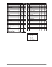
PARTS AND MAINTENANCE
When the life of the product has expired, it is recommended
that the product be disassembled, degreased and parts
separated by material so that they can be recycled.
The original language of this manual is English.
Refer all communications to the nearest Ingersoll Rand
O ce or Distributor.


